CPR Series Broadband Power Supply 36VDC and 48VDC Technical Manual TM Effective: March, 2004 ®
Power Alpha Technologies. Protecting The Power in Communications.
TM CPR Series Broadband Power Supply Technical Manual Effective: March, 2004 745-573-B0-001 REV. A — © 2004 Alpha Technologies NOTE: Photographs contained in this manual are for illustrative purposes only. These photographs may not exactly match your installation. NOTE: Review the drawings and illustrations contained in this manual before proceeding. If there are questions regarding the safe operation of this powering system, please contact Alpha Technologies or your nearest Alpha representative.
Preface Contents Important Safety Instructions ...................................................................................................................... 6 General Safety Precautions ....................................................................................................................... 7 Battery Safety Notes .................................................................................................................................. 9 Battery Maintenance Guidelines .........
Preface Figures & Tables 1.0 Overview Fig. 1-1, Fig. 1-2, Fig. 1-3, Fig. 1-4, Fig. 1-5, Ground Mount (Front View of 4 battery cabinet with ground skirt) ................ 14 Pole Mount (Front View of 8 battery cabinet) ................................................ 14 Pole Mount (Rear View of cabinet) ............................................................... 15 Typical Placement of Disconnect Breaker on rear of Cabinet .......................
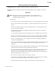
Preface Important Safety Instructions Contained In This Manual. Read This Manual Before Proceeding! Review the drawings and illustrations contained in this manual before proceeding. If there are any questions regarding the safe installation or operation of the system, contact Alpha Technologies or the nearest Alpha representative. Save this document for future reference.
Preface General Safety Precautions A “Warning” identifies conditions and actions that pose a hazard to the user. A “Caution” identifies conditions and actions that may damage the power supply or associated equipment. Warnings NOTE: This enclosure and its associated hardware (power supply, batteries, cabling) may contain equipment, batteries or parts which have accessible hazardous voltage or currents.
Preface General Safety Precautions Cautions NOTE: Enclosure, equipment or parts may be damaged or cause damage if used or installed improperly. To avoid damage: 8 • Prior to installation, verify that the AC input voltage to the enclosure and its equipment match with respect to voltage and frequency. • Prior to installation, verify that the output voltage from the enclosure or its equipment match the voltage requirements of the connected equipment (load).
Preface Battery Safety Notes Lead-acid batteries contain dangerous voltages, currents and corrosive material. Battery installation, maintenance, service and replacement must be performed by authorized personnel only. Chemical Hazards NOTE: Any gelled or liquid emissions from a valve-regulated lead-acid (VRLA) battery contain dilute sulfuric acid, which is harmful to the skin and eyes. Emissions are electrolytic, which are electrically conductive and corrosive.
Preface Battery Safety Notes, continued y Prior to handling the batteries, touch a grounded metal object to dissipate any static charge that may have developed on your body. y Never use uninsulated tools or other conductive materials when installing, maintaining, servicing or replacing batteries. y Use special caution when connecting or adjusting battery cabling.
Preface Recycling and Disposal Instructions y Spent or damaged batteries are considered environmentally unsafe. Always recycle used batteries or dispose of the batteries in accordance with all federal, state and local regulations. Electrical Safety y Lethal voltages are present within the power supply and electrical boxes. Never assume that an electrical connection or conductor is not energized.
Preface Mechanical Safety 12 y Keep hands and tools clear of fans. Fans are thermostatically controlled and will turn on automatically. y Power supplies can reach extreme temperatures under load. y Use caution around sheet metal components and sharp edges. 745-573-B0-001 REV.
1.0 Overview 1.1 1.0 Overview, Continued Introduction The Lectro CPR® Broadband Powering System is a result of an integrated approach that combines proven line-interactive UPS technology with rugged ferro technology. The tradtional advantages of a ferroresonant output, combined with high-capacity surge suppression, advanced microprocessor control, improved thermal performance and greater operating efficiency provide for a lighter, smaller, and more efficient unit.
1.0 Overview, Continued 1.2 Cabinet Nomenclature EXTERNAL INDICATOR LAMPS PADLOCK HASP GROUND SKIRT Fig. 1-1, Ground Mount (Front View of 4 battery cabinet with ground skirt) EXTERNAL INDICATOR LAMPS Fig. 1-2, Pole Mount (Front View of 8 battery cabinet) 14 745-573-B0-001 REV.
1.0 Overview, Continued 1.2 Cabinet Nomenclature, continued OPTIONAL LOCATION FOR "FEED-THRU" ADAPTOR GROUND AC INPUT CONDUIT CONNECTION POLE MOUNTING BRACKET Fig. 1-3, Pole Mount (Rear View of cabinet) DISCONNECT BREAKER BOX Fig. 1-4, Typical Placement of Disconnect Breaker on rear of Cabinet "FEED THRU" ADAPTOR AT REAR OF BOTTOM SHELF COAX SEIZURE CLAMP "SNAP IN" CONNECTOR (TO POWER SUPPLY INPUT) Fig. 1-5, Coax “Feed Thru” Adapter Normal Location (Bottom Shelf) 745-573-B0-001 REV.
2.0 Cabinet Installation, continued 2.1 Pole Mounting NOTE: Pole mounting the cabinet should be done in accordance with the local agreement between the cable operator and the utility company. NOTE: A bucket truck and other suitable equipment, such as spikes and safety harness, should be used during installation or service of pole-mounted cabinets. To mount the Lectro UPS to a utility pole perform the following steps: INSTALLATION PROCEDURE TM 1.
2.0 Cabinet Installation, continued 2.1 Pole Mounting, continued 2. Remove the U-shaped bracket from the cabinet rear panel. 3. Use the bracket as a template to mark mounting holes at the desired mounting location. If possible, position the cabinet so that the front panel and the external LED’s are easily visible. NOTE: If attaching to a concrete pole additional mounting hardware will be required for the installation. Lectro does not provide the metal bands required to mount to a concrete pole.
2.0 Cabinet Installation, continued 2.2 Ground Mounting Although ground mounting the CPR cabinet can be accomplished by several methods, the following procedure is recommended: INSTALLATION PROCEDURE 1. Select an appropriate site. Check with other local utilities for buried plant before site location is finalized. Remove the turf and level an area of approximately 4" greater than the footprint of the CPR cabinet. Refer to Figure 2-2 for details. TM 2.
2.0 Cabinet Installation, continued 2.2 Ground Mounting, continued INSTALLATION PROCEDURE, CONTINUED 8. Drill out the two holes in the template and insert two 5/8" X 4" (M16-2.0 x 100mm) bolts (not supplied). The heads of the bolts will be embedded into the concrete pad when installation is complete. Leave sufficient thread above the pad for securing the ground skirt. 9. Center the template (with holes in position) over the form.
2.0 Cabinet Installation, continued 2.3 Enclosure Grounding NOTE: Alpha Technologies recommends using the grounding method illustrated below. The grounding method for a particular site will be dependant upon soil type, available space, local codes, NEC (National Electric Code), and other site-specific characteristics. Alpha Technologies recommends 5 ohms minimum ground resistance between enclosure and ground rods, in accordance with IEEE 1100-1999 “Powering and grounding Electronic Equipment”.
2.0 Cabinet Installation, continued 2.4 Electrical Connections WARNING: Be sure the utility (mains) disconnect is off and that no conductors are energized before proceeding. CONNECTION PROCEDURE 1. Open the cabinet doors. 2. Install liquid tight conduit to the fitting on the cabinet rear panel and pull the AC primary into the cabinet housing. 3.
3.0 Power Supply, continued 3.1 CPR Module Installation and Connection TM NOTE: The CPR module weighs 56 lbs/25 kg. (65 lbs./30 kg for the 24 amp model), and the center of gravity is offset to the right. The unit may be lifted using both of the lifting handles on the front of the module. CAUTION: When pulling the unit forward from a shelf, be sure to support the right hand rear corner. INSTALLATION PROCEDURE TM 1. Verify the battery breaker on the front panel of the CPR is open (off). TM 2.
3.0 Power Supply, continued 3.1 CPR Module Installation and Connection, continued TM 5. If the batteries are not installed, install them at this time per the instructions in Section 3.2. Connect the battery sensing wire harness to the appropriate battery terminals as shown in Figure 3-7 or 3-8. Use appropriate flat washers when connecting this harness to small battery terminals.
3.0 Power Supply, continued 3.1 CPR Module Installation and Connection, continued TM A. B. C. D. E. D A B AC output cable Output voltage select Battery power cable (Fig. 3-5, 3-6) AC input Temp. probe connector E C Fig. 3-2, Connection points for 60Hz, 15A units A. AC output fitting D (Note: Green w/yellow trace and solid yellow cables may also be used for output connection.) A B C B. C. D. E. Output voltage select Battery power cable connection AC input Temp. probe connector A. B. C. D. E.
3.0 Power Supply, continued 3.2 Battery Installation and Connection CAUTION: Short circuit danger: Do not rest tools or equipment on top of batteries. Do not allow batteries to become shorted as an explosion may occur causing severe injury. Do not open or mutilate batteries. Released electrolyte is extremely harmful to skin and eyes. Do not dispose of batteries in fire as an explosion my occur. CAUTION: Government regulations may require that batteries be recycled.
3.0 Power Supply, continued 3.2 Battery Installation and Connection, continued 3.2.1 48V Battery Installation Procedure TM 1. Confirm the CPR DC circuit breaker is off (down). 2. Place the batteries in the bottom of the cabinet, negative terminals (-) at the rear of the cabinet. TM 3. Connect the red battery cable which comes from the gray connector on the CPR module to the positive (+) terminal of the left battery. Torque all connections to 60 inch-pounds (6.8 Newtonmeters). 4.
3.0 Power Supply, continued 3.2 battery Installation and Connection, continued 3.2.2 36V Battery Installation Procedure TM 1. Confirm the CPR DC circuit breaker is off (down). 2. Place the batteries in the bottom of the cabinet, negative terminals (-) at the rear of the cabinet. TM 3. Connect the red battery cable which comes from the red and black connector on the CPR module to the positive (+) terminal of the left battery. Torque all connections to 60 inch-pounds (6.8 Newton-meters). 4.
3.0 Power Supply, continued 3.2 Battery Installation and Connection, continued 3.2.3 Connecting an Additional 48V Battery String NOTE: This procedure assumes that the additional battery string is being installed in a Lectro brand cabinet. TM 1. Confirm the CPR DC circuit breaker is off (down). 2. Place the batteries in the bottom of the cabinet with the negative terminals (-) at the rear of the cabinet. 3.
3.0 Power Supply, continued 3.2 Battery Installation and Connection, continued 3.2.4 Connecting an Additional 36V Battery String NOTE: This procedure assumes that the additional battery string is being installed in a Lectro brand cabinet. TM 1. Confirm the CPR DC circuit breaker is off (down). 2. Place the batteries in the bottom of the cabinet with the negative terminals (-) at the rear of the cabinet. 3.
3.0 Power Supply, continued 3.2 Battery Installation and Connection, continued 3.2.5 Battery Removal 1. Turn the DC circuit breaker off (down) and observe all precautions for the safe handling of batteries as previously outlined. 2. Remove all batteries in the reverse order of installation.
3.0 Power Supply, continued 3.2 Battery Installation and Connection, continued BATTERY SENSE INPUT For Level 3 wiring, refer to manual P/N 040-0080-1501 OPTIONAL XM STYLE TEMPERATURE PROBE Red and Black Anderson Connector Negative (Black) RED BLACK UPPER SHELF Middle (Orange) - - - + + + TEMP PROBE INPUT LOWER SHELF Positive (Red) - - - + + + Middle, Longer lead (Orange) CABINET FRONT Fig.
3.0 Power Supply, continued 3.2 Battery Installation and Connection, continued BATTERY INPUT For Level 3 wiring, refer to manual P/N 040-0080-1501 OPTIONAL XM STYLE TEMPERATURE PROBE Gray Anderson Connector Negative (Black) RED BLACK UPPER SHELF - - - - + + + + Middle (Orange) CABINET FRONT TEMP PROBE INPUT Positive (Red) Middle Longer (Orange) If unused, tuck connector out of the way Fig. 3-11, Battery Sensing and Temperature Probe Connection – Single String 32 745-573-B0-001 REV.
3.0 Power Supply, continued 3.3 Operation CPR UPS STARTUP AND INVERTER TEST PROCEDURE: TM TM 1. Verify that all connections to the CPR have been made correctly as described in Section 3.1. 2. Verify that the desired output voltage has been selected (48V, 60V, 75V, or 87V) via the connection at the left side of the CPR module. Check to see that the AC input cord and Battery power cables are plugged in. TM 3.
3.0 Power Supply, continued 3.3 Operation, continued TM 7. Verify the external LEDs on the CPR outdoor cabinet are functioning. In normal operation, the green external LED will be ON solid, (not flashing). The green LED flashes when the CPR system is on battery, and the red LED flashes when there is a system alarm or failure. TM 8. INVERTER TEST: This test will verify proper operation of the system inverter. Push the front panel button labeled “Inverter Test.
3.0 Power Supply, continued 3.4 Maintenance 3.4.1 Routine Maintenance Checks NOTE: It is important that secure mechanical and electrical connections be maintained on this equipment. Secure connections will help prevent outages and equipment damage. Refer to the following page for a sample of a maintenance log sheet. 1. Inspect the external ground connections for mechanical integrity and good physical condition. Check the cabinet for damage and check the mounting hardware for mechanical integrity. 2.
3.0 Power Supply, continued 3.4 Maintenance, continued 3.4.2 CPR Power Supply Maintenance Log Sheet Use this form in conjunction with the maintenance procedures in the previous section.
3.0 Power Supply, continued 3.4 Maintenance, continued 3.4.3 Battery Storage Always make sure a battery is fully charged before placing it into storage. Never charge batteries in a gas-tight container. Always store batteries in a cool, dry location. Optimum temperature is 25°C (77°F). Always monitor battery, open-circuit voltage at least once every 12 months. If not using a Lectro CPR battery, refer to the manufacturer’s guidelines for storage.
4.0 Troubleshooting, Continued 4.1 Troubleshooting Guide Part 1 Because it is impossible to account for every possible symptom and solution in a CATV Network, the following troubleshooting suggestions should be used as a general guideline. SYMPTOM No AC output to coax cable Inverter does not run, or module does not transfer to "standby" either during a power failure or an "inverter test". CPRTM Module fails to transfer from "standby" back to "normal" mode after a utility outage.
4.0 Troubleshooting, Continued 4.2 Troubleshooting Guide Part 2 SYMPTOM AC input "High" red LED is lit. PROBABLE CAUSE AC input voltage is above 156 (or 299 for 230V nominal units, or 276 for 240V nominal units) VAC— unit will be in standby mode, running on battery. AC input "Low" red LED is AC input voltage is below 96 (or 161 for lit. 230V nominal units, or 192 for 240V nominal units) VAC— unit will be in standby mode, running on battery.
5.0 Status Monitor, Continued 5.1 Installation The communication module installs in the same basic manner for all three levels of status monitoring. The external connections will be different as defined in Section 4.3. 1. Turn off the CPR Unit, and remove AC Power. 2. Remove the communication module cover plate (if applicable). 3. Locate and pull out the ribbon cable with the connector, inside of the CPR Communicator TM module slot. 4.
5.0 Status Monitor, Continued 5.2 Operation The operation of the status monitor is automatic and carries out its functions without the direct intervention of the operator. The purpose of the status monitor is to indicate the operating conditions of the CPR power supply. There are three levels of status monitoring: LEVEL ONE Indicates locally (at the power supply) only. This can be a combination of the external cabinet LED indicators and/or the LED’s on the CPR power supply.
5.0 Status Monitor, Continued 5.2 Operation, continued LEVEL THREE Allows for remote status monitoring similar to Level One and Two with the DB-9 connector replaced by a F-81 style, 75-ohm, RF connector. This level is proprietary or HMS, and directly compatible with CheetahNet. Level Three is used to indicate remotely via an internal (inside the communicator module) RF transponder for use with CheetahNet. The F-81 connector is used to make the connection between the transponder and the CATV Network.
6. Specifications, Continued 6.
6. Specifications, Continued 6.1 Electrical, Mechanical Specifications, Continued MODEL 1 2 0 V 3 6 V E x td R ange PARAM ETER 2 3 0 V 3 6 V E u ro (C E ) N o m in a l I n p u t V o lt a g e 120V 230V I n p u t V o lt a g e R a n g e ( % ) + 3 0 % to -2 0 % + 2 0 % to -3 0 % 1 6 1 v to 2 7 6 V I n p u t V o lt a g e R a n g e 9 6 V to 1 5 6 V N o m in a l I n p u t C u r r .
Power www.alpha.com Protecting The Power in Communications. Alpha Technologies 3767 Alpha Way Bellingham, WA 98226 USA Tel: (360) 647-2360 Fax: (360) 671-4936 Web: www.alpha.com Alpha Technologies Ltd. 4084 McConnell Court Burnaby, BC, V5A 3N7 CANADA Tel: (604) 430-1476 Fax: (604) 430-8908 Alpha Technologies Europe Ltd.