
Operating instructions
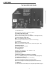
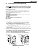

2. SIDE PANEL
THE XM SERIES SIDE PANEL
12
1. - AC Power Cord
(Connects to the enclosure's convenience outlet.)
2. - Standby Status Relay (SSR)
White (1) = Common; Red (2) = N.O. / N.C.
(Select contact normally open / closed with wire on back plane board.)
3. - Remote Indicator Lamp (LRI)
Black (3) = Negative; Red (4) = Positive
(Connects to pole-mount enclosure's optional external lamp)
4. - AC Output
White (5) = Neutral; Black (6) = Hot
(Connects to SPI Service Power Inserter; or ACI Lamp option / SPI)
5. - Battery Connector
Red = Positive; Black = Negative
(Connects to batteries)
6. - AC Output Fuse
(XM 6015 = 20A; XM 6012 = 15A; XM 6010 = 12A)
7. - Battery Circuit Breaker
(60 Amp magnetic)
8. - Main Circuit Module Assembly Access Handle
(Access to 10A Battery Charger fuse; APM and USM logic upgrades)
9. - USM Connector Access
(Used for status monitoring interface connections)
10. - Remote Temperature Sensor Connector (RTS)
(Connects to charger for exact battery temperature measurements)
11. - Data Port
(Used for data retrieval and diagnostic testing with optional DataLogger)
11
10
3 42 51
6
7 8 9