
Operating instructions

OPTIONAL FEATURES
The following options can be ordered factory installed or, in most instances, can be
field retrofitted by qualified service personnel.
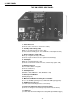
5.1 APM-XP (Automatic Performance Monitor)
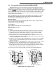
The APM-XP is a field replaceable, plug-in logic card that plugs directly into the edge
connector located on the back of the main circuit module. It upgrades the power supply's
standard logic functions to include a self-test feature that automatically tests the batteries
and inverter at pre-selected intervals. If a problem is detected during the self-test mode,
the APM activates an alarm circuit and flashes the red "CHECK BATTERIES" or "CHECK
INVERTER" LEDs, located on the front panel, to indicate the circuit that has failed the
test.
5.2 USM (Universal Status Monitor)
The USM is a field replaceable, plug-in logic card that allows the XP Series power
supply to be configured for pre-existing status monitoring systems. It can be configured
for parallel or serial applications. The USM facilitates use with common amplifier monitor-
ing systems such as Scientific Atlanta “6585” (SA), Magnavox “6DSS” (M), Jerrold “RSM”
(J), AM Communications “TMC-8061” (AM), Texscan “Vital Signs” (T) and C-COR “Quick
Alert” (C). For systems utilizing AlphaSoft status monitoring software, the USM-(A) can be
manipulated, manually or automatically, to provide information such as battery condition,
inverter operation, and alarm status.
5.3 LRI (Local and Remote Indicator)
Used in conjunction with APM and USM logic upgrades, the LRI lamp (red) is located
on the outside of pole-mount enclosures and duplicates the function of the module's
"STANDBY POWER" LED in the System Status block. The lamp comes ON only when
the power supply is running on backup power (STANDBY). During normal AC line opera-
tion, the lamp remains OFF. Whenever a fault is detected during the APM self-test, the
lamp flashes to indicate that service is required . The LRI can be used as a simple form of
status monitoring by allowing cable technicians to check the operational status of the
power supply without having to climb the pole and open the enclosure.
5.4 ACI (AC Indicator)
The AC Indicator (green) is located next to the LRI lamp on the outside of pole-mount
enclosures. The ACI is similar in function to the module's (green) "AC OUTPUT" LED in
the System Status block. As long as there is voltage present at the output, the ACI lamp
remains ON. As with the LRI, this acts as a simple form of status monitoring by allowing
cable technicians to check the output status of the power supply without having to climb
the pole and open the enclosure.
5.5 SDD (Standby Data Display)
The dual-function, "STANDBY DATA" display is used to keep track of accumulated
inverter run time, and to record the number of standby events. The "ELAPSED TIME"
clock is activated only during inverter operation. The "STANDBY EVENTS" counter
displays the number of standby events lasting longer than 60 seconds in duration.
5.6 SSR (Standby Status Relay)
On APM and USM units equipped with the "STANDBY STATUS RELAY," dry "Form
C" contacts are provided to accommodate systems requiring remote alarms. If, during the
APM self-test function, a fault is detected, the alarm circuit will activate. The contacts are
configured "common“ and "normally open” (contacts close when alarm is present). The
contacts can be reconfigured "normally closed” (contacts open when alarm is present) by
moving a wire located on the module's back plane board.
16
5. OPTIONAL FEATURES