
Operating instructions

6.8 Main Circuit Module Removal and Installation
The XM Series power module comes with a field-replaceable, main circuit module
assembly containing the standard control logic. It is designed to accept APM (Automatic
Performance Monitor) and USM (Universal Status Monitor) plug-in logic upgrades to
facilitate self-testing and status monitoring. The removable module is located on the left
side of the unit.
CAUTION: ALWAYS SWITCH THE BATTERY BREAKER OFF PRIOR TO REMOVING OR
INSPECTING THE MAIN CIRCUIT MODULE ASSEMBLY.
DO NOT REMOVE THE MODULE ASSEMBLY DURING INVERTER OPERATION.
HANDLE THE CARD ASSEMBLY WITH EXTREME CARE. CIRCUIT BOARDS AND LOGIC
UPGRADES ARE STATIC-SENSITIVE AND SUSCEPTIBLE TO DAMAGE. HANDLE THE
CARD ASSEMBLY WITH EXTREME CARE. CIRCUIT BOARDS AND LOGIC UPGRADES
ARE STATIC-SENSITIVE AND SUSCEPTIBLE TO DAMAGE.
WHEN RE-INSTALLING THE MODULE, MAKE SURE THE CARD EDGE CONNECTOR IS
FIRMLY SEATED IN THE BACK PLANE ASSEMBLY.
Procedure:
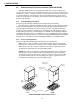
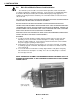
1. To remove the main module assembly, grasp the handle on the left side of the unit.
Pull firmly to release the module from the back plane assembly. Gently slide the
module assembly straight out. It is designed so that the board can be removed while
the power supply is operating on AC line power.
2. Verify that the correct battery charge voltages are selected (section 6.9). If an APM
or USM logic upgrade is included, "Auto-Equalize" and "Auto-Test" switches must be
set (section 6.10).
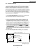
3. To reseat the main circuit module assembly, align it with the card guides and gently
slide it back into the back plane assembly. Press the assembly firmly to seat it into
the card edge connector.
6. INSTALLATION
28
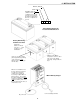
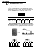
Main Circuit Module
Module Assembly
(pulls straight out)
NOTE: THE MODULE ASSEMBLY CAN BE REMOVED WHILE THE POWER SUPPLY IS
RUNNING ON LINE POWER. IT WILL CONTINUE TO OPERATE AS A NON-STANDBY
POWER SUPPLY.