
Operating instructions

6.11 USM (Universal Status Monitor),
continued
6. INSTALLATION
33
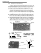
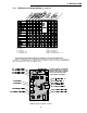
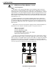
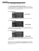
USM Pin Jumper and Switch Locations
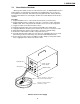
CAUTION: HANDLE ASSEMBLIES
WITH EXTREME CARE. CIRCUIT
BOARDS AND LOGIC UPGRADES
ARE STATIC-SENSITIVE AND
SUSCEPTIBLE TO DAMAGE.
KEY:
O = Open
C = Closed
1 = Short pins 1 & 2
3 = Short pins 2 & 3
SWITCH SETTINGS
Parallel Configurations:
Address = 0; Mode = 0
Serial Configurations:
Address = 001-999; Mode = 1-6
Select the pin and switch settings according to your specific application.
Example: If configuring for a Jerrold RSM (USM-J): P1 requires the jumper across pins 1 & 2; P2 has the
pin jumper closed; P3, P4, P5, P6 have their pin jumpers open; P7 is set to the 15V position; P8, P9, P13, P14
require their jumpers across pins 2 & 3; SW4 is set to 0.