
Operating instructions
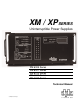

Table of Contents
1. INTRODUCTION 1
1.1 The XP Series Uninterruptible Power Supply
1.2 Theory of Operation
1.2.1 AC (LINE) Operation
1.2.2 Inverter (STANDBY) Operation
1.2.3 Charger Operation
1.3 Specifications
2. FRONT PANEL 6
2.1 APM (Automatic Performance Monitor) Status Block
2.1.1 "TEST/RESET" Switch
2.1.2 "NOT INSTALLED" LED
2.1.3 "TEST IN PROGRESS" LED
2.1.4 "CHECK BATTERIES" LED
2.1.5 "CHECK INVERTER" LED
2.2 Charger Status Block
2.2.1 "CHARGE MODE" Switch
2.2.2 "FLOAT" LED
2.2.3 "EQUALIZE" LED
2.2.4 "RECHARGE" LED
2.3 System Status Block
2.3.1 "LINE POWER" LED
2.3.2 "STANDBY POWER" LED
2.3.3 "AC OUTPUT" LED
2.4 Output Current Display
2.4.1 LED Display
2.5 SDD (Standby Data Display)
2.5.1 "MODE" Switch
2.5.2 "ELAPSED TIME" LED
2.5.3 "STANDBY EVENTS" LED
2.5.4 Time/Events Window
3. SIDE PANEL 12
3.1 AC Power Cord
3.2 Standby Status Relay (SSR)
3.3 Remote Indicator Lamp (LRI)
3.4 AC Output
3.5 Battery Connector
3.6 AC Output Fuse
3.7 Battery Circuit Breaker
3.8 Main Circuit Module Access Handle
3.9 USM Connector Access
3.10 Remote Temperature Sensor Connector (RTS)
3.11 Data Port
XP Series Uninterruptible Power Supplies
i