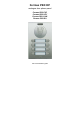
Fermax PBX DP analogue door phone panel Fermax PBX EXP Fermax PBX KEY Fermax PBX CAM Fermax PBX EA User and installation guide
Welcome Congratulations on purchasing the door phone panel “Fermax PBX Door Phone” Fermax PBX DP. This door phone can satisfy your need of communication with visitors at the entrance to the building, to your company or at the entrance of your house. Its use is universal, because it can be connected to an analog internal extension line of your PBX regardless on its type or on the producer. To each pushbutton you can program up to two 16-digit numbers in pulse or tone dialling incl.
Manual version V8.1 6. 4.2010 Contents 1 BASIC DESCRIPTION....................................................................................... 6 1.1 FEATURES ...................................................................................................... 6 1.2 ASSEMBLY OF PANELS ................................................................................... 7 1.2.1 Terminology and orientation in panels ..................................................... 7 1.2.2 Examples of panels .........
4.8 4.9 5 TECHNICAL PARAMETERS ........................................................................ 37 5.1 5.2 6 OVERVIEW OF PARAMETERS ........................................................................ 34 LIST OF PRESETTING PARAMETERS .............................................................. 36 ELECTRICAL PARAMETERS .......................................................................... 37 MECHANICAL DIMENSIONS ..........................................................................
1 Basic description 1.
1.2 Assembly of panels The building blocks of Fermax IP DP are the basic panels which differ by its size, number of pushbuttons, if the visit card has got two or one pushbuttons. 1.2.1 Terminology and orientation in panels 4 AP 204 (item number) as a representative of terminology. It is a panel with height of 199mm. It contains an audio module and two times 4 pushbuttons, i.e. 8 pushbuttons in total. first digit: 1 - 9 defines the height of the whole panel, the width of all panels is 130mm.
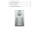
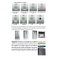
1.2.2 Examples of panels Fermax PBX DP 1 AP 201 Fermax PBX DP 2 AP 202 Fermax PBX DP 1 AP 101 Fermax PBX DP 2 AP 201 Fermax PBX EA 1A Fermax PBX KEY 1 Fermax PBX EA Fermax PBX CAM 2A 2C All panels can be mounted either on the surface or they can be flush mounted. In the latest catalogue of Fermax you can choose the correct New Cityline accessories incl. for example the protective roofing. Fermax PBX DP panels can be equipped with an additional time switch called "TimeRelay".
Please do not use systems which do not support DTMF transmission during the call from the wireless DECT phone to the other wireless DECT phone (e.g. DTMF transmission is required when you need to use the DTMF command for opening the door). DistyBox has got its own power supply. it works as a DECT to analog line convertor. The door phone panel is connected to this analogue line.
1.3 Characteristics of the modules 1.3.1 The basic module of electronics Fermax PBX DP The basic module of Fermax PBX DP panel is supplied in two versions – with two pushbuttons - Fermax PBX DP-2 (a version for 1 or 2 pushbuttons) and two pushbuttons with a possibility of expansion by additional 8 pushbuttons, i.e. each basic panel allows connection of up to 10 pushbuttons with no further accessories of Fermax PBX DP panel.
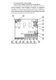
Picture 2 The real image of connection and set-up elements 1. Service jumper is used usually in case when the user forgets the service password for entering into the programming mode. The standard way of entering into the programming mode is by calling the line where Fermax PBX DP is connected, the door phone answers the call and then you dial the service password #xxxx where xxxx is the password. In the default settings the service password is xxxx=0000. This way you can enter the programming mode.
3. Loudspeaker loudness SPK – you can set the desired loudspeaker loudness/volume with the trimmer. Attention – the louder the loudspeaker volume, the sharper the switching of echo cancellation (TRH settings). You can obtain approx. 25mW from the telephone line for the acoustic output of the Handsfree circuit, therefore further increasing of the loudness volume just leads to higher distortion.
11. 12. 13. 14. or for 12V - 24VDC (direct), max. cnsumption is 250mA (+ 3,5mA x number of visit cards).
15. Connector 8 - for connecting 8 pushbuttons (integrated expansion). For connection please use an interconnection cable Fermax PBX CC8. Each colour of the cable is assigned exactly for a specific pushbutton – see picture 3.
1.3.2 Example of switches connection The switching contact of relay is separated galvanically from other circuits of the door phone panel. Also 12V power supply is separated galvanically from the rest of the circuits. 1.3.3 Front panel 1. Assembly openings for mounting of the front panel. After installation of the top opening, please cover it with the plastic cover with Fermax logo. When bottom opening please cover with the grey, round plastic cover. Both covers incl.
can also find a red LED under the visit card – it is used for signallisation of the door phone panel status. 5. Microphone 1.3.4 Exchange of visit cards The visit cards are disassembled from the front of the door phone panel as shown on the picture. Please use a tool carefully, do not damage the front panel or the cover of visit cards. The cover of visit cards is a tub into which you place the paper with description (the visit card). 1.3.
The numbering of positions is shown on the picture 5. All numbers of pushbuttons refer to the settings of the door phone panel (see more in the programming section). All numbers are related to setting of the door phone "6#0" (see the programming part of the manual). It means the basic panel uses two firmly mounted pushbuttons on the main PCB board. In the table above one is deducted from the number of the pushbbuton when setting 6#1, two is deducted from the number of pushbutton when setting 6#2.
1.4 Assembly of the door phone panel 1.4.1 Surface mounting For surface mounting we offer a compact installation box. The installation box is mounted with screws with plugs to the wall. On the picture you can find an installation box, size 1. 1.4.2 Flush mounting Flush mounted installation boxes are refered to as “MKxx” or simply “flush mount installation boxes”.
When installing the door phone panel in the environment where water may be condensing (temperature changes) or where it may be raining on the door phpje panel, we suggest to use the jumper on the main PCB board – turn on the heating. Main PCB board heating has got two positive functions. Firstly it warms up the electronics during winter when temperatures drop below -20°C (most components have got guaranteed parameters for temperatures up to -20°C).
2 Door Phone NUDV (Fermax PBX DP) Operation 2.1 Signaling Overview The Door Phone NUDV (Fermax PBX DP) signals an acoustic conditions they may occur during operation. Another signaling can be done by means of red LED (placed under microphone hole). You can listen the signaling samples in Nset setting program.
guard will lift up the line neither immediately (the button is not the first number from code lock), or with delay (parameter 53) and after period given by parameter 55 will dial the programmed phone number. The dialing number differs by choice mode, which is set in the guard (parameter 47): - Day/night mode = being the guard in Day mode, so it is always dialing a number set in parameter 1, in Night mode, it is always dialing a number set in parameter 2. The mode switchover is set in parameters 45,46.
- number is stored (same as for buttons). The number dialing is managed by Day/Night setting or mode for two groups of numbers (as described in Chapter 2.2.1). Version of firmware 7.8 makes it possible dial DTMF dialing during talk from keyboard. This feature it is possible switch on only by programming from phone, from PC program this feature isn't accessible and after programming door phone possibility dial from keyboard during talk is OFF.
3 Programming of Parameters 3.1 Programming through Phone 3.1.1 Entry to Programming The New Door Phone NUDV will be set to programming mode in two ways: 1. by password – only incoming call! – answer the telephone and dial a number, where the guard is lined (either branch number, if connected to branch exchange or number of state line to object, where the guard is placed and let you put through to branch directly connected with guard). The guard will answer (you hear tone for answering – see Chapter 2.
will be sufficient and the guard immediately responds by error tone, but he will extend the period to hanging up.. Note 2. The # sign is not used by entering of 32,33,34 parameters can be used for immediate parameter entering. 3.2 Programming from PC – Program Nset To guard’s setup by means of personal computer (PC) the special KAB cable to serial port and Nset program should be available and the guard has to be connected to telephone line.
4 Description of Parameters 4.1 Direct Dialing – Memories Parameter Value 1 tt nn… Meaning Basic No. nn under button tt - tt – Button number (memory), always set in two-digit manner [01-64] nn – telephone number up to 16 digits, we want to store. To store other choice flags the assignment given in table is mean. choice 0-9 0-9 used. # # The numbers stored in parameter 1 are the number of the first group or numbers of Day mode.
m=3 lighting mode – it will close by guard lifting up and stay closed even for ss period after guard hanging up (the line is engaged for this period). m=4 switch mode – it will close after button pressing and open after ss period (used for e.g. external bell or horn connections). m=5 gradual opening mode – in this mode the only switch 2 will be set together with switch 1 set to mode 1. The switch 1 is activated for ss period, then the time xx is proceeding before switch 2 closing.
The same command can be set for both switches, then they are activated at the same time. The advantage is to set the same command both for switch closing and command to guard hanging up (parameter 43) aa=bb.
Parameter Value 42 z Meaning Basic * sign for call extension z – sign for call extension * or # (10sec before call end the guard will send a notice, then the call may be extended) List of related parameters: 52 8# 84 Parameter Value 43 g bb Meaning command for guard hanging up from phone Basic 155 266 g – command order [1-2] (two commands in order to hang up the guard using both switches) bb – command for guard hanging up from phone [2 digits] The advantage is to set the same command both for switc
Parameter Value 48 c Meaning Basic 0 keyboard connection c – c=0 only NC-mode connected to the basic module c=1 the keyboard connected on the first position c=2 the keyboard connected on the second position c=3 the keyboard connected on the third position ATTENTION !! This parameter setting will sharply influence whole guard function.
Parameter 52 Value d Meaning 53 Value w 2 max. call time d – max. time, for which the guard is hanging up, this time can be extended during call by sign choice from telephone (* or #). Time setting is per table. List of related parameters: 42 8# 85 Parameter Basic Meaning time [min] 0,5 1-9 15 30 choice 0 1-9 * # Basic 2 time among button presses w – max.
Parameter 55 Value z Meaning Basic 1 time before dialing z – time [sec] after guard lifting up before dialing [range 1-5]. This time is different for each exchange, but most central exchanges usually manage to process dialing up to 2 seconds after line lifting up. List of related parameters: 8# 85 Parameter Value 56 hh Meaning Basic 12 number of rings before hanging up h – after finishing the dialing it calculates number of KVT (ringing tones).
4.5 Presetting and Deleting Parameter Value 8# # Meaning Basic executes basic setting This setting does not influence 1 and 2 (numbers stored in memory) Parameter Value 81 82 83 84 85 Meaning deletes all numbers in group 1 (Day mode) deletes all numbers in group 2 (Night mode) basic setting only for parameters 3x basic setting only for parameters 4x basic setting only for parameters 5x Basic only 3.. only 4.. only 5..
4.7 System Setting Parameter Value 6# s Meaning Basic number of non-fitted buttons of basic module The basic module is fitted with 2 buttons as standard, i.e. s = 0, s = 1 is set up for basic module with one button and s = 2 for module without buttons. This setting is a factory one, no service can change it and so it is recommended not to change this parameter. Note: Connecting.
4.8 Overview of Parameters Parameter Value Meaning Basic 1 tt nn… No. nn under button tt - 2 tt nn… No. nn under button tt - 31 rm switch r works in m mode 11 21 32 pasw. hhhhhh for r switch in DAY + NIGHT r hhhhhh mode - 33 r hhhhhh pasw. hhhhhh for r in DAY mode - 34 r hhhhhh pasw.
57 t DTMF tone duration (tone) choice 5 (100ms) 58 m gap duration among DTMF tones 5 (100ms) 59 f Flash duration 1 (100ms) 50 p pause duration / interdigit gap 8 (800ms) 8# # basic setting executes 81 82 83 84 85 9 deletes all numbers in group 1 (Day mode) deletes all numbers in group 2 (Night mode) basic setting only for parameters 3x basic setting only for parameters 4x basic setting only for parameters 5x END only 3.. only 4.. only 5..
4.9 List of Presetting Parameters parameter switch 1 mode switch 2 mode passw.Day+Night switch 1 passw. Day+Night switch 2 passw.Day switch 1 passw.Day switch 2 passw. Night switch 1 passw. Night switch 2 switch 1 activ. from phone switch 2 activ. from phone closing time of switch 1 and 2 con. by incoming call delay among ap. during oper.
5 Technical Parameters 5.1 Electrical Parameters Parameter Minimum line current Minimum line voltage Voltage on line while guard answers (VA characteristics) Leakage in hang up status Impedance of line termination Band width Impedance of ringing Sensitivity of ringing detector Pulse choice Tone choice level Tone choice sensitivity Sensitivity of tone detector Power supply of lighting through, switches and heating Max. consumption of lighting through and heating Max. voltage of switch contact Max.
6 Table for Easy Programming Complete the values in empty part of table you want to program. In double-frame part there are whole programming commands, so the programming is very simple and without errors. Furthermore such programmed values will be available for next changes in manual. Meaning Description Programming sequence Spec. par. Complete your values num.
Password for switch 1 Password for switch 2 Password for switch 1 Password for switch 2 Password for switch 1 Password for switch 2 Day+Night Day+Night Day Day Night Night 6 [sec] [sec] 1/0 1/0 321 322 331 332 341 342 351 352 361 362 371 372 [sec] 38 2 1/0 */# 1. 2. 41 42 431 432 44 45 46 47 48 49 40 1 1 Clos. of switch 1 fr. phone Clos. of switch 2 fr. phone Closing time of switch 1 Closing time of switch 2 Sw. cont.1 by incoming call Sw. cont.
Pause durat.
Guarantee conditions: The product was shop-checked. The producer guarantees that this product will keep the features described in these operating instructions in the course of guarantee provided that the user will be handled with it as described in the operating manual. The guarantee will be extended by period of possible guarantee repair. When claiming in guarantee period please contact your dealer. The producer only will make the guarantee repairs.
© JR 2010 version V8.