
Installation guide
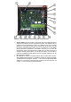


3. Loudspeaker loudness SPK – you can set the desired loudspeaker
loudness/volume with the trimmer. Attention – the louder the loudspeaker
volume, the sharper the switching of echo cancellation (TRH settings). You
can obtain approx. 25mW from the telephone line for the acoustic output of
the Handsfree circuit, therefore further increasing of the loudness volume
just leads to higher distortion. In case you need to increase the volume
output, you can use an extrernal loudspeaker module with an amplifier
Fermax PBX EA.
4. Connection of loudspeaker SPK
5. Settings of acoustic coupling TRH is used for balancing of direction on the
telephone line (outgoing-incomming voice transmission). To avoid “hooting”
of the door phone because of the acoustic coupling, the door phone
chooses which direction (outgoing-incomming) has got the priority, if the
priority will be given to the microphone direction or to the loudspeaker
direction. The sound volume level of “swtching” the microphone direction of
the door phone is set with the trimmer „TRH“. The settings of this trimmer is
influenced by the level of surrounding noise and setting of microphone
volume „MIC“ and loudspeaker volume "SPK".
Process of the set-up: please set the trimmers MIC and SPK to ¼ from the
minimum sound volume (from the minimum value start turning to the left),
the trimmer TRH needs to be set to the middle position. During the voice
connection please speak softly and start turning the TRH trimmer to the left
side until the other party on the phone side (inside the building) starts
hearing you well. Increasing the volume of the loudspeaker or the
microphone then can be set as required according to local conditions.
6. Please pay attention on the correct polority during the connection of a
microphone MIC!
7. The loudness of microphone MIC is set by the trimmer. Please bear on
mind that the louder the sound volume, the sharper the switching of echo
cancellation (set-up of TRH).
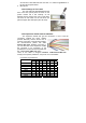
8. Jumper Heat (marked as H) enables switching on/off the heating which is
integrated on the main board for the door phone. The heating has got
automatic regulation, therefore it works both at 12V or 24V power supply .
The lower the temperature, the higher the output of the heating (max.
1,5W).
9. Jumper Light (marked as L) enables switching on/off the illumination of visit
cards.
10. Connection 12V – the connector for connection of power supply, which is
necessary just for the heating of the main board, for illumination of the visit
cards or for controlling the coils of relay contacts. The coil of relay has got
a consumption of 50mA, however the telephone line can supply e.g. 20mA
only. Therefore the coils of relay are controlled from the external power
supply of 12V by optrons (opto-isolators). If the power supply of 12V is not
connected, then you can´t verify contacts making! The circuits inside the
door phone have been designed for connection of 8V - 18VAC (alternating)