
Installation guide
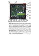


15. Connector 8 - for connecting 8
pushbuttons (integrated expansion). For
connection please use an
interconnection cable Fermax PBX
CC8. Each colour of the cable is
assigned exactly for a specific
pushbutton – see picture 3.
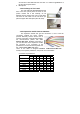
Connection of pushbuttons:
blue = 3rd pushbutton
brown = 4th pushbutton
yellow = 5th pushbutton
red = 6th pushbutton
white = 7th pushbutton
green = 8th pushbutton
orange = 9th pushbutton
black = 10th pushbutton
All numbers of pushbuttons are related to the setting of the door phone
"6#0" (see more in the programming part of the manual). It means the
basic panel with two pushbuttons is being used. These two pushbuttons
are used pernamently on the main PCB board. In the table please deduct 1
from the number of the pushbuttons when set to 6#1 and please deduct 2
from the number of the pushbutton when set to 6#2.
16. Connector 5 – connection of the 8-pushbutton expansion Fermax PBX
EXP or the keypad Fermax PBX KEY. The connection is done via Fermax
PBX CC5 cable. It is a data connection only. Power supply of illumination
and the common output is on the Connector 3.
17. Connector 3 - it is used for connection of the power supply and the
common output of the pushbuttons. The original Fermax cable is used
(Fermax PBX CC3).
Picture 3 Cable Fermax PBX CC8