
Installation guide
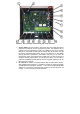


The numbering of positions is shown on the picture 5. All numbers of
pushbuttons refer to the settings of the door phone panel (see more in the
programming section). All numbers are related to setting of the door phone
"6#0" (see the programming part of the manual). It means the basic panel uses
two firmly mounted pushbuttons on the main PCB board. In the table above
one is deducted from the number of the pushbbuton when setting 6#1, two is
deducted from the number of pushbutton when setting 6#2.
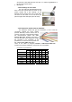
1.3.6 Keypad module Fermax PBX KEY
The keypad module is connected via a cable Fermax PBX CC5 and a
cable Fermax PBX CC3. The connection is similar to the connection of the
expansion module. The difference is that the keypad module is always the last
in the row (you cannot connect to the keypad module any other module). The
keypad module can be only connected to the second position (i.e. directly to
the basic module) or to the third position (to the output of the first Fermax PBX
EXP module). Attention – 1st position can´t be used because the first
position is occupied by the fixed expansion on the basic module
(pushbuttons 3-10). This means that besides the keypad you can use 0 – 18
pushbuttons with the direct dialling (depends on the specific configuration).
Please pay attention during programming – you need to specify correctly
to which position the keypad is connected (parameter 48).
Dialling is realised by a sequent pushing of number
pushbuttons. When entering a password, you need to press
the B pushbutton. To hang up, please press the pushbutton
A and the door phone panel hangs up. By parameter 40 you
can also enable dialling during the call.
1.3.7 Other modules (panels)
All other panels can be found in the offer of your local partner.
Picture 5 Connection of expansion modules