DoorPhone VoIP IPDPS – 01C IPDPS – 02C IPDPS – 01 IPDPS – 02 Installation and Operating Instructions
Welcome We congratulate you on purchase of “DoorPhoneSlim VoIP” (VoIP = Voice over IP), which is the improved version of successful “New DoorPhone” (NUDV). This DoorPhone VoIP will widely manage to satisfy your needs of communication with persons at the building front door or your company entry, or family house doorway. The universality lies in possibility to connect this guard to an Ethernet network or VoIP exchange or directly to SIP server through internet conection.
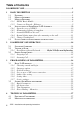
Table of Contents DOORPHONE VOIP ...............................................................................................1 1 BASIC DESCRIPTION ...................................................................................5 1.1 FEATURES ..................................................................................................5 1.2 MODULE ASSEMBLY ...................................................................................6 1.3 MODULE FEATURES ......................................
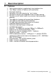
1 Basic Description 1.1 Features Ø Ø Ø Ø Ø Ø Ø Ø Ø Ø Ø Ø Ø Ø Ø Ø Ø Ø Ø Ø Voice communication is supplied only from telephone line Two 16digit numbers (IP adress) with each button Day/night switching Possibility of the call extension by * or # choice Possible to connect two independent locks for door opening Possible use of 5 switch modes (e.g.
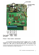
1.2 Module Assembly The IPDPS are the basic modules with color camera IPDPS-01/02C or without camera IPDPS-01/02. IPDPS-01 IPDPS-02 IPDPS-01C IPDPS-02C 1.3 Module Features 1.3.1 IPDPS Basic Module The IPDPS basic module assembling from modulus IP and motherboard. Positioning setting elements and connectors is on picture 1. For IPDPS is necessary used the AC voltage of min. 10Vst - max. 15Vst or DC voltage of min. 12Vss to max. 18Vss must be energized to “12V” terminal.
Picture 1 Basic module - motherboard The connection of relay contact terminals is shown on fig. 1. The “NO” designation means an idle-disconnected contact, “COM” means a pin contact (middle) and “NC” means an idle-connected contact. The contacts of both switches are galvanically isolated each other and from other guard circuits. The variants of connection are shown on picture. 2.
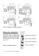
Picture 2 Examples of relays connections Setting voice communication – position trimmers are presetting from manufacture and in majority case agree with, therefore changes setting altering only in necessary case. Basic position of trimmers, sense of rotation and meaning trimmers are illustration on picture 3.
DIP switch setting basic operation and default setting. See on picture 4. Picture 4 DIP switch settings 1.3.
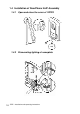
1.4 Installation of DoorPhone VoIP Assembly 10 1.4.1 Open and close the cover of IPDPS 1.4.
1.4.3 Assembly IPDPS on the wall The installation is made by screwing to the wall by means of dowels. 1.4.4 Return lighting name plate after mounting on the wall.
1.4.5 Change of nameplates Each button has its separate nameplate hold by means of plastic flag (see figure). The paper nameplates can be printed from Excel form (to be downloaded on www.alphatech.cz).
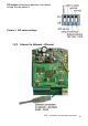
1.5 Focus camera and description of front panel If is need focus picture from camera, so everything is illustration on picture basic module on Picture 5 . Picture 5 camera in IPDPS 1. VoIP module 2. connect microphone 3. connect speaker 4. camera 5.
2 DoorPhone VoIP Operation 2.1 Signaling Overview The all-purpose guard signals an acoustic conditions they may occur during operation. Another signaling can be done by means of red LED (placed under microphone hole). You can listen the signaling samples in Nset setting program.
set in m=1 or m=5 modes) to the period given by seting in parameters. Then it will hang up. 2.3 Person Inside Object The person inside object is considered a person that is in phone contact with DoorPhone. 2.3.1 Outgoing Call The outgoing call is the call from DoorPhone (caused by visitor). After guard choice the telephone is ringing inside object and the pickuping up will allow speaking to the visitor at door.
3 Programming of Parameters 3.1 Basic VoIP settings 3.1.1 Choosing a mode and login It is important to choose a DoorPhone mode first. The DoorPhone can work in the PeerToPeer mode or SIP server mode. The mode setting can be made by a relevant switch (DIP switch see on picture 8). In the SIP server mode is possible to choose SIP server (external). It can be set in a configuration interface of the DoorPhone. Picture 6 DIP switch setting In your web browser enter IP address of the DoorPhone, default is 192.
3.1.2 Language option Language setting can be made in a menu on the left panel. 3.1.3 Network settings Network settings are located in the Network seting menu item. It is possible to use DHCP service (1) or you can enter IP addresses manually. Manual configuration: After making changes click on a save and restart button. 1 –Enable/disable ethernet settings via DHCP 2 –Default value – presetings to the firm settings.
DHCP configuration: After making changes click on a save and restart button. 1 –Enable/disable ethernet settings via DHCP 2 –show automatic DHCP generate IP adress and othet settings 3 –Default value – presetings to the firm settings. After making changes click on a save and restart button (display screen - see page 21).
3.1.4 Peer to peer or SIP server connection The DoorPhone can be set to the peer to peer (P2P) mode or to the SIP server mode by DIP switch (page 16). In P2P mode DoorPhone calling IP adress – in memory buttons (page 26). If you setting SIP server mode by DIP switch, so add in menu item SIP parameters After making changes use the save changes button.
3.1.6 Setting video After making changes use the save changes button. 1 –Resolution display video 2 –Number picture per second (frequency restoring picture) 3 –Setting next parameters of camera 4 –Default value – presetings to the firm settings. After making changes use the save changes button.
3.1.7 Service settings 1 –display current version of firmware in module VoIP and in module doorphone, button switching if is has save history events in basic or enhanced mode - it is important to analyses mistakes and problems. This file it is possible save to PC by click on download log file. 2 –tool for upgrade firmware in module VoIP and in module doorphone, switching automatic - information is in upload fille.
3.2 Setting DoorPhone parameters 3.2.1 Basic Parameters After making changes use the save changes button. 1 –Mode of DoorPhone choice selects number per Day/Night DoorPhone mode or selects numbers of the first and second groups. 2 –Sign for call extension * or # (10sec before call end the DoorPhone will send a notice, then the call may be extended) 3 –Two commands in order to hang up the DoorPhone using both switches [2 digits].
3.2.2 All about relays After making changes use the save changes button. 1 – Relay mode: =1 switch mode – it will close on command or password for period t1/2 (used for electrical locks, gate opening etc.) =2 camera mode – it will close by guard pick up and open by hanging up. =3 lighting mode – it will close by guard pick up and stay closed even for period t1/2 after guard hanging up. =4 bell mode – it will close after button pressing and open after period t1/2 (used for e.g.
2 –password for relay closing from buttons or keyboard [2 to 6 digits]. Total 6 passwords, they are controlled by Day/Night; the combination is entered either by DoorPhone buttons (first 1/2 buttons) or from attached keyboard (after pressing of key symbol). The relay closing influences the set switch mode and Day/Night switchover. By setting of choice mode of 2 number groups the DoorPhone is permanently in DAY mode.
3.2.3 Time Parameters After making changes use the save changes button. 1 –max. time, for which the DoorPhone is hanging up, this time can be extended during call by sign choice from telephone (* or #) – see page 22. 2 –Number of incoming call rings, the DoorPhone pick up after preseted number of rings. After detection first ring – LED on front panel blinking. The number can be set from 1 to 9. 3 –max.
3.2.4 Direct Dialing – Memories After making changes use the save changes button. 1 –telephone number up to 16 digits, we want to store. The numbers are the numbers of the first group or numbers of Day mode. In default setting is table memoirs empty. While using setting P2P to the memoirs saves IP address e.g . 192*168*1*250, where „*“ means „.“ , while using SIP proxy server to the memoirs saves phone number e.g. 117. 2 –telephone number up to 16 digits, we want to store.
4 Technical Parameters 4.1 Electrical Parameters Parameter Value Communication interface VoIP protocol supported Band width Power supply of lighting through, switches and heating Max. consumption Max. voltage of switch contact Max. current of switch contact Operational temperature Conditions Ethernet 10BaseT, 100BaseTx SIP 300Hz – 3400 Hz 12Vss ± 2V , 10-12Vst ± 2V 300mA 48V 2A 12Vss at I < 1A at U < 30 V - 20 to + 50°C 4.
Guarantee conditions: The product was shop-checked. The producer guarantees that this product will keep the features described in these operating instructions in the course of guarantee provided that the user will be handled with it as described in the operating manual. The guarantee will be extended by period of possible guarantee repair. When claiming in guarantee period please contact your dealer. The producer only will make the guarantee repairs.
© JR 2008 version V5.