
Operation Manual


ALPINE MRV-V500 68-29530Z24-A (EN/FR/ES)
11-EN
EN
FR
ES
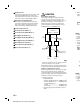
SYSTEM DIAGRAMS
Front Speakers
Rear Speakers
Subwoofer
Head Unit, etc.
Front Output
Rear Output
Subwoofer Output
RCA Extension Cable (Sold Separately)
Y-Adapter (Sold Separately)
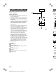
TYPICAL SYSTEM CONNECTIONS
4 Speaker + 1 Subwoofer System (5-Channel Input)
Input Channel Selector Switch Setting
3/4 SUB W.
CH-3/4 SUB W.
White Violet/Black
FR
Gray/Black RL Green
RL
Green/Black
RR
Violet
RR
Violet/Black
White/Black Violet
FR
Gray
Gray Green/Black
FL
White/Black
Gray/Black Green
FL
White
Connecting to the Speaker Level Input System
1 For the “Speaker Level Input System” setting,
connecting the Remote Turn-On Lead is not
required due to the “REMOTE SENSING” function of
this product. However, the “REMOTE SENSING”
function may not work depending on the signal
source connected. In such a case, connect the
Remote Turn-On Lead to an incoming power
supply cord (accessory power) in the ACC position.
2 If connecting both Speaker Input Leads and RCA
Inputs at the same time, do not connect both
signals to the same input channel of the amplifier.
Instead, be sure to connect each pair of inputs to a
different Input channel pair.
example;
Speaker Input Leads:
FL/FR to CH1/CH2, RL/RR to CH3/CH4
RCA Inputs:
SUBWL/SUBWR to SUBWL/SUBWR
Fig. 10
to a
e cause.
dicator
lt your
to a