R EN PXA-H701 MULTIMEDIA MANAGER™ FR • OWNER'S MANUAL Please read before using this equipment. ES • MODE D'EMPLOI Veuillez lire avant d’utiliser cet appareil. • MANUAL DE OPERACIÓN Léalo antes de utilizar este equipo. ® ALPINE ELECTRONICS MARKETING, INC. 1-1-8 Nishi Gotanda, Shinagawa-ku, Tokyo 141-0031, Japan Phone 03-5496-8231 ALPINE ELECTRONICS OF AUSTRALIA PTY. LTD. 6-8 Fiveways Boulevarde Keysborough, Victoria 3173, Australia Phone 03-9769-0000 ALPINE ELECTRONICS OF AMERICA, INC.
ENGLISH Before using The control unit for the PXA-H701 is sold separately. The operation method using this control unit (sold separately) is printed in this instruction manual. However, if you use head units such as the IVA-D300 or the IVA-D900, you can also operate the PXA-H701 from these head units (Items such as AUTO TCR and navigation system voice guidance interruption settings can only be operated from the Control Unit).
WARNING WARNING This symbol means important instructions. Failure to heed them can result in serious injury or death. DO NOT OPERATE ANY FUNCTION THAT TAKES YOUR ATTENTION AWAY FROM SAFELY DRIVING YOUR VEHICLE. Any function that requires your prolonged attention should only be performed after coming to a complete stop. Always stop the vehicle in a safe location before performing these functions. Failure to do so may result in an accident.
PRECAUTIONS Temperature Be sure the temperature inside the vehicle is between +60°C (+140°F) and –10°C (+14°F) before turning your unit on. Installation Location Make sure the PXA-H701 will not be installed in a location subjected to: • Direct sun and heat • High humidity and water • Excessive dust • Excessive vibrations FR Maintenance If you have problems, do not attempt to repair the unit yourself. Return it to your Alpine dealer or the nearest Alpine Service Station for servicing.
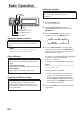
Basic Operation Setting the speakers CHANNEL ENTER First make the speaker settings. Turn off speaker channels that are not connected. 1 SETUP Rotary encoder 2 PRO LOGIC II indicator Dolby Digital indicator DTS indicator 3 Press the SETUP button. The setup mode is set. Turn the Rotary encoder to select the “SPEAKER SELECT” mode, then press the ENTER button. Press the CHANNEL button to select the speaker, then press the ENTER button.
Using with Ai-NET connections When Ai-NET connections are used, the volume, subwoofer, balance and fader are adjusted from the head unit (they cannot be adjusted from the PXA-H701). However, BASS and TREB can not be adjusted from the head unit, so adjust them from PXA-H701. Adjusting the input level Using the analog, RCA-type connections, the PXA-H701’s input level must be preset from the head unit. Adjust the input level using a sound source with a high recording level (such as pop or rock music).
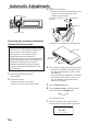
Automatic Adjustments 3 AUTO TCR ENTER Connect the microphone. 1) Fasten the microphone included with control unit at the center of the driver’s seat’s headrest facing upwards. To microphone input jack Microphone Belt, etc. Rotary encoder Performing time correction automatically (Automated Time Correction) Due to the particular conditions inside the vehicle, there is a major difference between the distances of the various speakers and the listening position.
With the automatic adjustment function, the operation described below is performed. Adjustments are completed in about 10 seconds. Time correction. “END” is displayed for about 15 seconds and the automatic adjustment is completed. • EN If the microphone does not pick up the sound or the speakers are not working or are connected or wired improperly, the automatic adjustments are not performed and a error message is displayed. Check the various speakers then perform the automatic adjustments again.
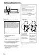
Settings/Adjustments TCR/PHASE CHANNEL ENTER • Concrete examples 1.Calculating the time correction value for the front left speaker on the diagram below. Conditions: Distance between farthest speaker and listening position: 2.25 m (88-3/4") Distance between front left speaker and listening position: 0.5 m (20") Calculation: L = 2.25 m (88-3/4") – 0.5 m (20") = 1.75 m (68-3/4") Compensation time = 1.75 ÷ 343 x 1000 = 5.
6 Press and hold the CHANNEL button for at least 2 seconds and select “L and R (LR)” or “L or R”. L and R (LR) 0 L and R (LR): Sets the same adjustment values for the left and right channels. L or R: Different adjustment values can be set for the left and right channels. Press the CHANNEL button and select the desired channel, then press the ENTER button. When “L and R (LR)” is selected: Front 1 Front 2 Turn the Rotary encoder to switch the phase, then press the CHANNEL button.
Settings/Adjustments 5 TCR/PHASE CHANNEL ENTER 6 7 B.C. Rotary encoder 8 Bass Focus The time difference between the front-rear/leftright speakers, can be adjusted a pair at a time. Audible time correction can be made from 0.05 ms to 20.00 ms in 401 steps (0 to 400). 1 2 3 4 Check that the defeat mode is off. (See page 28.) Press the TCR/PHASE button to select the time correction mode. Press the B.C. button to select the “BASS FOCUS” setting mode.
Example of Steps 4 and 5 Setting 1.After entering corrections for the front (left and right) speakers in STEP 30, the time difference is 1.5 ms for both front-left and front-right speakers. 1.5ms 1.5ms 2. After entering corrections for the left (front and rear) speakers in STEP 30, the time difference becomes 3.0 ms* for the front left speaker, and 1.5 ms for the left rear speaker. * Because the time difference was already set to 1.
Settings/Adjustments *3 When center is set to subwoofer, it becomes Sub.W(R). G.EQ 5 CHANNEL ENTER Turn the Rotary encoder to select the frequency, then press the ENTER button. Adjustable frequencies Front/Rear/Center: 20Hz~20kHz (1/3 octave step) Sub.W: 20Hz~160Hz (1/3 octave step) 6 P.EQ Rotary encoder Turn the Rotary encoder to adjust the level (± 9 dB in steps of 1 dB), then press the ENTER button. 3 1 –G .
Parametric equalizer adjustments 6 The frequency bands of the graphic equalizer are fixed. This makes it very difficult to correct for undesired peaks and dips at specific frequencies. The parametric equalizer’s center frequency can be tuned these specific frequencies. Then, the bandwidth (Q) and level are fine-tuned, independently, to make the necessary corrections. The parametric equalizer function is an advanced tool for serious audiophiles. 1 2 3 P . EQPF r o n t L BAND : 4 Fc : 3 .
Settings/Adjustments CHANNEL ENTER P.EQ 9 Repeat steps 5 to 8 to adjust other bands. 10 To adjust other channels, press the CHANNEL button to return to step 4. * To compare the factory default settings (DEFEAT ON) with your newly adjusted parametric equalizer settings (DEFEAT OFF), do the following: 1) While in the adjustment mode, press and hold the P.EQ button for at least 2 seconds. 2) Press the P.EQ button to switch the defeat mode on and off and listen to the difference in the sound.
X-OVER Signals with these frequencies output The PXA-H701 is equipped with an active crossover allowing the frequency bands to be split before amplification. Because of this, there is no need for a passive network between the speakers and amplifiers. This makes the amplifiers fully independent, eliminating the problem of interference. This also makes it possible to achieve the optimum acoustic space by dividing the playback frequencies in a way suited to the speaker’s response.
Settings/Adjustments *1 When center is set to subwoofer, it is not displayed. *2 When center is set to subwoofer, it becomes Sub.W(L). *3 When center is set to subwoofer, it becomes Sub.W(R). X-OVER CHANNEL ENTER 5 Rotary encoder X – OVE PR F r o n t HP f c : 3 5 0 HP s l o p e : 1 2 LPf c : 1 . 8k LPs I op e : 6 X-OVER adjustment This section describes the procedure for making the X-OVER adjustment. Before performing this procedure, see “X-OVER” on page 15.
Hint for adjusting the subwoofer • If the subwoofer is installed on the rear deck, setting a gentle L.P.F. slope (for example 6 dB/ oct.) makes the sound localization more to the rear. This can also affect the acoustic localization of the front. EN Hints for adjusting the high range • Depending on the speaker, inputting low frequency component signals (about 2 kHz or less) with the H.P.F. adjustment could result in distortion. If so, set a steep slope (for example 30 dB/oct.).
Settings/Adjustments FM: MX1 to 3 and OFF The medium to high frequencies become more clear, and produces well balanced sound in all the bands. CD: MX1 to 3 and OFF CD mode processes a large quantity of data. This data is used to reproduce the sound cleanly by making use of the data quantity. MP3/XM: MX1 to 3 and OFF This corrects information that was omitted at the time of compression. This reproduces a well-balanced sound close to the original.
3 4 Turn the Rotary encoder to select the source (media) you want to set, then press the ENTER button. Turn the Rotary encoder to select the desired mode, then press the ENTER button. For further information about setting mode, see step 3 of 1 (page 18). EN NOTE This function is equipped to work anywhere in the world, and it is possible to set to “DAB”. This mode is a specification developed for use abroad, but like “MP3/XM", can have the same effect as “MX” .
Using Dolby Surround * If DOLBY PL II MUSIC is selected, the center width can be adjusted with following operations. This function offers the optimum vocal position by adjusting the center channel position between the center speaker and the L/R speaker. (The adjustments established in “Adjusting the acoustic image” (page 24) are ineffective while this function is activated.) 1) After selecting DOLBY PL II MUSIC, within PLII/ 15 seconds, press and hold the REAR FILL button for at least 2 seconds.
Adjustment procedure for Dolby Surround Make the adjustments described below in order to reproduce Dolby Digital and DTS sound with greater accuracy.
Using Dolby Surround OFF: When no speaker is connected SMALL: When a speaker that cannot play low frequencies (80 Hz or less) is connected LARGE: When a speaker that can play low frequencies (80 Hz or less) is connected *1: It is not possible to set the front speakers to “OFF”. *2: If the front speakers are set to “SMALL”, the rear and center speakers cannot be set to “LARGE”. CHANNEL ENTER SETUP Rotary encoder 6 Press the SETUP button repeatedly to quit the setup mode.
4 Turn the Rotary encoder to select “Auto”, then press the ENTER button. Test tone output is repeated for each of the different speaker channels. They will be repeated in the order shown below. If no operation is performed for 2 seconds, the channel switches to the next channel.
Using Dolby Surround 5 ENTER 6 SETUP Rotary encoder Adjusting the acoustic image In most installations, the center speaker must be placed directly between the front passenger and driver. Using this function, the center channel information is distributed to the left and right speakers. This creates an acoustic image simulating a center speaker directly in front of each listener. Adjusting the center width in DOLBY PL II MUSIC (see “Using the Pro Logic II mode”, page 20), makes this function ineffective.
Achieving powerful high volume sound With Dolby Digital, the dynamic range is compressed so that powerful sound can be achieved at regular volume levels. This compression can be canceled to achieve an energetic sound with even greater power, like the sound in a movie theater. NOTE This function works only in the Dolby Digital mode. 1 2 3 4 Press the SETUP button. The setup mode is set. Turn the Rotary encoder to select the “5.1CH SETUP” mode, then press the ENTER button.
Convenient Functions 6 Press the SETUP button repeatedly to quit the setup mode. NOTE For connection with navigation, refer to the "Installation and Connections" (page 40). ENTER Linear PCM setting SETUP The output when playing discs recorded in linear PCM can be set to 2 or 3 channels.
Display settings The display’s contrast and LCD (negative/ positive) can be adjusted. 1 2 3 4 5 Press the SETUP button. The setup mode is set. Turn the Rotary encoder to select the “DISPLAY SETUP” mode, then press the ENTER button. Turn the Rotary encoder to adjust “CONTRAST”, then press the ENTER button. Adjust the contrast (color depth) between –8~+8 so that the display is easy to see. Turn the Rotary encoder to perform the “LCD MODE” setting, then press the ENTER button.
Convenient Functions Calling out stored values 1 Press any button from 1 to 6 to select the preset memory you want to call out (“MEMORY1” to “MEMORY6”). In the preset memory, numerous settings/ adjustments are stored. Therefore, it may take some time to access the stored preset memory. L OA D I NG DEFEAT 1~6 DISP PRESET MEMORY 1 NOTE This operation can only be performed when the defeat mode is turned off. Storing settings in the memory This function can store up to 6 adjustments/ settings.
Switching the display mode 1 Press the DISP button to select the desired display mode. Spectrum analyzer display(1~3) Input channel display Display OFF Example of input channel (When monaural surround signal (s) is not inputted) EN Preset No. I N P U T CH P– 2 P L C R L FE L s S Rs The display changes according to the input signals. The indicated items are highlighted when there is no input.
Installation and Connections Before installing or connecting the unit, please read the following and pages 2 and 3 of this manual thoroughly for proper use. Warning DO NOT DISASSEMBLE OR ALTER. Doing so may result in an accident, fire or electric shock. USE THE CORRECT AMPERE RATING WHEN REPLACING FUSES. Failure to do so may result in fire or electric shock. MAKE THE CORRECT CONNECTIONS. Failure to make the proper connections may result in fire or product damage.
ARRANGE THE WIRING SO IT IS NOT CRIMPED OR PINCHED BY A SHARP METAL EDGE. Route the cables and wiring away from moving parts (like the seat rails) or sharp or pointed edges. This will prevent crimping and damage to the wiring. If wiring passes through a hole in metal, use a rubber grommet to prevent the wire’s insulation from being cut by the metal edge of the hole. DO NOT INSTALL IN LOCATIONS WITH HIGH MOISTURE OR DUST. Avoid installing the unit in locations with high incidence of moisture or dust.
Installation and Connections IMPORTANT Please record the serial number of your unit in the space provided below and keep it as a permanent record. The serial number plate is located on the bottom of the unit. Accessories Ai-NET cable Connection Cable Velcro fastener for mounting control unit or base unit x2 SERIAL NUMBER: INSTALLATION DATE: INSTALLATION TECHNICIAN: Flanged selftapping screw (M4 x 14) PLACE OF PURCHASE: To prevent external noise from entering the audio system.
3 Installation Mount the control unit using the included screws. Bracket Mounting the control unit (Sold Separately) Spacer CAUTION: Do not install the control unit near the air-bag of the front passenger’s seat. • Confirm the installation location will be safe. • Determine the mounting position on the dashboard. The area should be large enough to center the unit and reasonably flat.
Installation and Connections 3 Mount the spacer and bracket to the control unit. Next, securely mount the factory brackets removed from the factory radio, to the control unit assembly. 4 Mount the spacer on the control unit using the included screws. Spacer Flat head screws (M5 x 8) Control unit Pan head screw (M3 x 5) x 2 5 Attach the flush mount brackets to the control unit using the included screws. Mount this assembly into the prepared cut-out.
Mounting the base unit ● Velcro Fastener Mounting ● Using the Mounting Screws (Supplied) The Base Unit can be mounted under the seat using the mounting screws. 1 2 3 Decide on the installation location. • The trunk, etc., is the best place. Mark the positions of the mounting screws at the chosen location. Drill 3 mm (1/8”) holes or smaller. WARNING When making holes, be careful not to damage pipes, tanks, electric wires, etc. Doing so could lead to accidents or fire.
Installation and Connections Basic Connections Diagram CAUTION Do not connect or disconnect the display cable when the power of the unit is on. Display (Sold Separately) Terminal specifications Connect to: • Head unit input terminal (optical digital input) Used for system expansion (Ai-NET head unit, etc.). Connect to an Ai-NET product using an optical fiber cable. • Changer input terminal (optical digital input) Used for system expansion (Ai-NET changer, etc.).
Examples of system expansion • PXA-H701 + Ai-NET Compatible Head Unit + DVD Changer + Monitor + External Amplifier Fiber Optic Cable (Sold Separately) ★ Remote Control Output Cable Monitor (TME-M790 etc.
Installation and Connections • PXA-H701 + Ai-NET Compatible Head Unit + CD Changer + External Amplifier Fiber Optic Cable (Sold Separately) ★★ Fiber Optic Cable (Sold Separately) ★ Ai-NET Cable (Included with CD Changer) ★★★ Ai-NET Compatible CD Changer Ai-NET Cable (Included) Ai-NET Compatible Head Unit CENTER SELECTABLE SUBWOOFER (L) CD/DVD H.U.
• PXA-H701 + Head Unit + Video Deck etc. + External Amplifier • For connecting a head unit with which Ai-NET connections are not possible. Blue/White Blue/White * Remote OUT cable Remote ON Cable RCA connection cable Head Unit Ai-RCA Conversion Cable (Sold Separately) RCA connection cable TV Tuner, Video etc. Audio Output CENTER SELECTABLE SUBWOOFER (L) CD/DVD H.U.
Installation and Connections • PXA-H701 + IVA-D300 Head Unit + CD Changer + Navigation System + External Amplifier White/Green White/Green Guide Control Cable Guide Control Cable NAVIGATION INPUT GUIDE OUTPUT NTSC VIDEO OUTPUT RGB OUTPUT NTSC RGB VIDEO OUTPUT Navigation REMOTE INPUT KCE-900E (Sold Separately) RCA connection cable RGB Cable (Sold Separately) Fiber Optic Cable (Sold Separately) IVA-D300 Head Unit Fiber Optic Cable ★ (Sold Separately) Ai-NET Cable (Included with CD Changer) ★★ Ai
Information Terminology Dolby Digital Dolby Digital is a digital audio compression technology developed by Dolby Laboratories that allows large quantities of audio data to be efficiently recorded on discs. It is compatible with audio signals from mono (1 channel) all the way up to 5.1-channel surround sound. The signals for the different channels are completely independent, and since the sound is high quality digital there is no loss of sound quality.
Others In case of difficulty If you encounter a problem, please review the items in the following checklist. This guide will help you isolate the problem if the unit is at fault. Otherwise, make sure the rest of your system is properly connected or consult your authorized Alpine dealer. Set does not operate. Nothing appears on the display. • Vehicle’s ignition key is turned off. - Turn the vehicle’s ignition key on. • Set’s power is not turned on.
Specifications Graphic EQ number of bands: Front (left and right) 31 bands Rear (left and right) 31 bands Center 31 bands Subwoofer 10 bands Graphic EQ boost cut range: ±9 dB Parametric EQ number of bands: Front/rear/center 5 bands Subwoofer 2 bands Parametric EQ frequency: Front, Rear and Center Band 1: 20/22/25/28/31.
GARANTIE LIMITÉE Fidèles à leur engagement de ne fournir que des produits de qualité, ALPINE ELECTRONIQUE DE L'AMERIQUE INC. et ALPINE ELECTRONIQUE DU CANADA INC. (Alpine) sont heureuses de vous offrir cette garantie. Nous vous suggérons de le lire attentivement et en entier. Si vous avez la moindre question, veuillez contacter l'un de nos concessionnaires ou appeler directement Alpine au numéros Liste ci-dessous.
LIMITED WARRANTY ALPINE ELECTRONICS OF AMERICA, INC. AND ALPINE OF CANADA INC. ("Alpine"), are dedicated to quality craftsmanship and are pleased to offer this Warranty. We suggest that you read it thoroughly. Should you have any questions, please contact your Dealer or Alpine at one of the telephone numbers listed below. ● PRODUCTS COVERED: This Warranty covers Car Audio/Visual Products and Related Accessories ("the product"). Products purchased in the Canada are covered only in the Canada.