Points to Observe for Safe Usage • Read this manual carefully before starting operation and use this system safely. We cannot be responsible for problems resulting from failure to observe the instructions in this manual. • This manual uses various pictorial displays to show how to use this product safely and to avoid harm to yourself and others and damage to your property. Here is what these pictorial displays mean. Understanding them is important for reading this manual.
Contents / Contenu Installation / Installation Parts List / Liste des pièces ................................................................................... 3 Woofer Installation / Installation du Woofer ............................................................ 4 Midrange Installation / Installation du haut-parleur médial .................................... 5 Tweeter Installation / Installation du Tweeter .........................................................
Parts List / Liste des pièces Woofer / Woofer 2 1 X2 5 4 3 X2 X2 X2 6 X10 7 X10 Français English 5 Screw M4 x 12 6 Screw ø4 x 19 1 Unité principale 2 Bague de la grille 5 Vis M4 x 12 6 Vis ø4 x 19 3 Grille 4 Adapter Ring 7 Hexagonal Wrench 3 Grille 7 Clé hexagonale 4 Bague d’accouplement English/Français 1 Main Unit 2 Grille Ring Midrange / Haut-parleur médial 8 p 9 X2 q X2 X6 X2 Français English p Grille q Screw ø4 x 19 8 Main Unit 9 Grille Ring p Grille 8 Unité principale
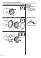
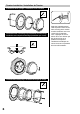
Woofer Installation / Installation du Woofer Speaker Wire Connections / Raccordement des fils d’enceinte Installation without a grille / Installation sans grille 6 X5 Installation with a grille / Installation avec grille 6 X5 Installation with adapter rings / Installation avec bagues d’accouplement 6 5 X5 4 X4 1. Insert the speaker wires through the connection holes. / Insérer les fils d’enceinte dans les trous de raccordement. 2. Fasten with a hexagonal wrench. / Serrer avec une clé hexagonale.
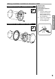
Midrange Installation / Installation du haut-parleur médial Speaker Wire Connections / Raccordement des fils d’enceinte Installation without a grille / Installation sans grille q X3 q Insert the speaker wires through the connection holes. / Insérer les fils d’enceinte dans les trous de raccordement. 2. Fasten with a hexagonal wrench. / Serrer avec une clé hexagonale. English/Français Installation with a grille / Installation avec grille 1.
Tweeter Installation / Installation du Tweeter Installation with springs / Installation avec ressorts i X1 Installation with a mounting cup (Installation from the front)/ Installation avec coupelle de montage (Installation par l’avant) a X1 Installation with fastening rings / Installation avec bagues de serrage u X5 6 Apply the supplied terminal cover to prevent short circuits from occurring when metallic or other conductors are in the vicinity of the installation area.
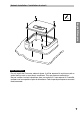
Network Installation / Installation du circuit g X3 English/Français Note /Remarque: Do not install the Crossover network where it will be exposed to moisture such as under the floor mat or near the air conditioner. This may cause a malfunction./ Ne pas installer le circuit répartiteur dans un endroit où il sera exposé à l’humidité, comme sous la moquette ou près du climatiseur. Cela risque de provoquer un mauvais fonctionnement.
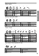
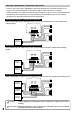
Network connections / Connexions du circuit Insert the signal link jumpers highlighted in gray firmly following each connection example. If the jumper is not connected properly as described, it might result in malfunction of amplifier. Insérez fermement les cavaliers de liaison de signal soulignés en gris en suivant chaque exemple de raccordement. Si le cavalier n’est pas relié correctement comme décrit, il pourrait avoir comme conséquence le défaut de fonctionnement de l’amplificateur.
Crossover Network Introduction It is common knowledge that the automotive interior is one of the most inhospitable environments for high-fidelity sound, and that every vehicle poses its own unique set of installation and acoustic challenges. While many of these problems can often be overcome with proper speaker placement, equalization, or other techniques, the attempt is a time consuming task without guaranteed results.
Jumper Group Function Although recommendations are made for the most common system types in the following pages, there are actually over 1000 unique and useful jumper combinations available for a wide variety of vehicles, installations and personal tastes. While this flexibility has obvious advantages, too many choices can also be confusing.
MID HP/LP: As a selectable bandpass filter for the midrange, the net effect of this section is naturally linked to the selections made in the tweeter high-pass and woofer low-pass sections. Achieving the most phase coherent and flat summation possible requires controlling the amount of inherent phase shift of each filter, and is directly related to the selection of filter order, Q and cut-off frequency.
Jumper Group Function WF-LP: While functioning as a low-pass filter for the woofer, this section also provides a wide degree of adjustments for optimizing performance and system integration. Since it is often difficult to position the woofer and midrange close together or at equal distances, it is critical to achieve phase linkage between them to avoid localization, image smear, poor staging, etc.
System Type 1 System Description With all three drivers mounted close together and equidistant to the listening position, this is surely the most favorable configuration for a component speaker system. Although such an installation may not often be practical in situations other than the demoboard, it is certainly possible given the custom fabrication techniques available today.
System Type 1 Network Jumper Setting Type-1A: Pathlength to the listening position is considered to be basically equal in this case (ideally 2-3m away), with relative on-axis positioning of all drivers. Phase linkage is accomplished with a low Q 2nd Order high-pass filter on the tweeter, 1st Order lowpass and 4 th Order high-pass on the midrange, and a semi-4th Order low-pass on the woofer. This results in acoustic crossover points of 3.8kHz and 700Hz respectively.
Network Jumper Setting Type-1B: While the mounting configuration is the same as Type-1A, this network setting provides a variation for when personal taste, positioning or vehicle acoustics necessitates more high frequency output from the midrange and tweeter. Rear deck installation is one particular example where the extreme off-axis positioning will require such level compensation due to the natural rolloff.
System Type 2 System Description As one of the more common applications, this installation type is the most likely to be accommodated by factory speaker locations to some degree, thus requiring the least amount of custom fabrication. However, due to the mounting arrangement and surface orientation, it also results in significant differences in distance and angle of all three drivers relative to the listener.
Network Jumper Setting Type-2A: For the tweeter in this case, pathlength from the listening position is considered to be 85cm, at approximately 1520° off-axis. Located at a moderate vertical distance down from the tweeter and basically flush to the panel, the midrange is 8.5cm farther away and presents a listening angle of about 40-50°. Due to the low door woofer location however, the listening angle for the woofer is close to 60° off-axis, with its acoustic center 8cm farther relative to the mid.
System Type 2 Network Jumper Setting Type-2B: Tweeter and midrange positioning are the same as in Type-2A, but the woofer is located farther forward. This results in a more extreme woofer listening angle of approximately 70°, with a delay of 28cm relative to the mid. Subsequently, level attenuation is applied to both the tweeter and mid while also adjusting filter characteristics appropriatly for the mid/woofer transition.
System Type 3 System Description Although the midrange and tweeter are mounted close together in this case, space limitations, aesthetics or practicality requires that the woofer be mounted separately. Utilizing the kick panel and door locations is the most common method, though it is certainly not the only one.
System Type 3 Network Jumper Setting Type-3A: Both midrange and tweeter are at the same distance and angle, while the woofer position is closer and fairly off-axis to the listening position. Therefore, the acoustic center of the woofer is considered to be the closest driver by approximately 18.5cm. In order to minimize overlap while maintaining phase coherence between the mid and woofer, a 3rd order high-pass and semi-2nd order low-pass are applied, resulting in a summation point of 600Hz.
Network Jumper Setting Type-3B: Despite the fact that the midrange and tweeter are mounted in the same plane and in close proximity, their orientation results in the acoustic center of the midrange being farther away. Therefore, the midrange is considered to be 8.5cm farther than the tweeter, while the woofer is approximately 25cm closer than the midrange.
System Type 4 System Description In this system type, some level of external signal processing is available, allowing use of the network in a partially active mode. Although speakers may be mounted in a wide variety locations in this case, it is recommended that traditional techniques be used regarding both positioning and placement. Fully active systems have often been considered to be the most flexible, but they are certainly not the most effective or practical in all cases.
Network Jumper Setting TW HP HP-1 LP-2 HP-2 HP-2 HP-1 LP-1 +2dB MID HP/LP HP-3 BYPASS MID HP/LP –3dB –1.5dB 0dB/0° +4dB/30° — SPX–Z18T HP-BYPASS LP-3 LP-2 LP-1 BYPASS + LP-BYPASS WF/MID SIGNAL LINK WF LP +1.5dB/15° TW LEVEL MID/TW SIGNAL LINK + — English Notes: • The +4dB/30° setting in the TW LEVEL jumper group bypasses all resistors in the tweeter section.
24
Introduction au circuit répartiteur Tout le monde sait que l’intérieur d’une voiture n’est pas l’environnement le plus hospitalier pour le son haute fidélité, et que chaque véhicule possède ses propres défis d’installation et d’acoustique. Alors que la plupart des problèmes peuvent être surmontés grâce à un placement adéquat des enceintes, grâce à l’égalisation ou à d’autres techniques, cela prend du temps et aucun résultat n’est garanti.
Fonction de groupe cavalier Bien que les recommandations des pages qui suivent soient destinées aux types de système les plus communs, il y a en fait plus de 1000 combinaisons de cavaliers différentes et pratiques, disponibles pour une grande variété de véhicules, d’installations et de goûts personnels. Bien que cette flexibilité possède des avantages évidents, un si grand choix peut également mener à la confusion.
MID HP/LP: Cette section fonctionnant comme un filtre passe-bande sélectionnable pour le hautparleur médial, son effet de réseau est naturellement lié aux sélections faites dans les sections du filtre passe-haut du tweeter et du filtre passe-bas du woofer.
Fonction de groupe cavalier WF-LP: Lorsqu’elle fonctionne comme un filtre passe-bas pour le woofer, cette section offre également un grand degré de réglages pour l’optimisation des performances et de l’intégration du système. Puisqu’il est souvent difficile de placer le woofer et le hautparleur médial près l’un de l’autre ou à des distances égales, il est difficile d’obtenir une liaison de phase entre eux pour éviter la localisation, le marbrage d’image, la pauvreté de mise en scène, etc.
Type de système 1 Description du système Lorsque les trois amplificateurs sont montés proches les uns des autres et à égale distance de la position d’écoute, il s’agit certainement de la configuration la plus favorable pour un système. Bien que ce type d’installation ne soit pas souvent pratique si ce n’est sur le panneau de démonstration, elle est certainement possible étant donné les techniques de fabrication personnalisées disponibles de nos jours.
Type de système 1 Réglage du cavalier du circuit Type-1A : La longueur de chemin jusqu’à la position d’écoute est supposée à peu près identique dans ce cas (2-3 m idéalement), avec un positionnement dans l’axe de tous les amplificateurs. La liaison de phase est accomplie par un filtre passe-haut 2ème ordre avec coefficient Q faible sur le tweeter, un filtre passe-bas de 1er Ordre et un filtre passe-haut de 4ème Ordre sur le haut-parleur médial et un filtre passe-bas de semi-4ème Ordre sur le woofer.
Réglage du cavalier du circuit Type-1B : Tandis que la configuration de montage est la même que pour le Type-1A, ce type de circuit fournit une variation pour les cas où les goûts personnels, la position ou l’acoustique du véhicule nécessitent une plus grande sortie haute fréquence depuis le haut-parleur médial et le tweeter. L’installation sur la plage arrière est un exemple particulier où le positionnement très en dehors de l’axe nécessitera ce type de compensation de niveau à cause de la pente naturelle.
Type de système 2 Description du système Etant l’une des applications les plus communes, ce type d’installation est celui qui a le plus de chances d’être utilisée lors du positionnement d’enceintes en usine, dans une certaine mesure, et cela demande alors moins de fabrication personnalisée. Cependant, à cause de l’arrangement de montage et de l’orientation de la surface, cela entraîne également des différences considérables de distance et d’angle des trois amplificateurs par rapport à la position d’écoute.
Réglage du cavalier du circuit Type-2A : Dans ce cas, pour le tweeter, la longueur du chemin depuis la position d’écoute est de 85cm, à environ 15-20° en dehors de l’axe principal. Situé à une distance verticale modérée en dessous du tweeter et sur le même plan que le tableau de bord, le haut-parleur médial est 8,5 cm plus loin et présente un angle d’écoute d’environ 40-50°.
Type de système 2 Réglage du cavalier du circuit Type-2B : La position du tweeter et du hautparleur médial est la même que dans le Type-2A, mais le woofer est situé plus loin vers l’avant. Cela entraîne un angle d’écoute du woofer plus extrême d’environ 70°, avec un retard de 28cm par rapport au hautparleur médial.
Type de système 3 Description du système Bien que le haut-parleur médial et le tweeter soient montés proches l’un de l’autre dans ce cas, les contraintes d’espace, l’esthétique et l’aspect pratique requièrent que le woofer soit monté séparément. Le panneau d’auvent et les portes sont les endroits de montage les plus courants mais ce ne sont certainement pas les seules.
Type de système 3 Réglage du cavalier du circuit Type-3A : Le haut-parleur médial et le tweeter sont à la même distance et au même angle tandis que le woofer est situé plus près et assez en dehors de l’axe de la position d’écoute. C’est pourquoi le centre acoustique du woofer est considéré comme étant l’amplificateur le plus proche à environ 18,5 cm.
Réglage du cavalier du circuit Type-3B : Malgré le fait que le haut-parleur médial et le tweeter soient montés sur le même plan et à proximité l’un de l’autre, leur orientation fait que le centre acoustique du haut-parleur médial est plus loin. C’est pourquoi il est considéré que le haut-parleur médial est 8,5 cm plus loin que le tweeter, tandis que le woofer est environ 25 cm plus près que le haut-parleur médial.
Type de système 4 Description du système Dans ce type de système, un certain niveau de traitement de signal externe est disponible, ce qui permet l’utilisation du circuit d’une manière partiellement active. Bien que les enceintes puissent être montées à de nombreux endroits, il est recommandé d’utiliser les techniques traditionnelles en ce qui concerne le positionnement et le placement.
Réglage du cavalier du circuit TW HP HP-1 LP-2 HP-2 HP-2 HP-1 LP-1 +2dB MID HP/LP HP-3 BYPASS MID HP/LP –3dB –1.5dB 0dB/0° +4dB/30° — SPX–Z18T HP-BYPASS LP-3 LP-2 LP-1 BYPASS + LP-BYPASS WF/MID SIGNAL LINK WF LP +1.5dB/15° TW LEVEL MID/TW SIGNAL LINK + — Remarques : • Le réglage +4dB/30° dans le groupe cavalier TW LEVEL court-circuite tous les résistors dans la section du tweeter.
External dimensions / Dimensions externes Woofer dimensions/Dimensions du woofer ) 2" 9 6.6 0( 192.7(7.586") 182(7.165") 148(5.826") 114(4.487") 7 φ1 φ5.3(0.20 8") 76.2(2.999") 10.6(0.417") 25(0.984") 5-72 ° Midrange dimensions/Dimensions du haut-parleur médial 2") 115.1(4.531") 93(3.661") 67(2.637") 45.4(1.787") 8.1(0.318") 40 φ1 φ4.2(0.165") 3-120 ° 124.9(4.917") .06 2(4 03. 16.8(0.
Tweeter dimensions/Dimensions du tweeter 5.3(0.208") 85(3.346") 76(2.991") 90(3.543") 78(3.07") 30.7(1.208") English / Français 25.1(0.988") 31(1.22") 13.75(0.543") Network dimensions/Dimensions du circuit 167.7(6.602") 230(9.054") 68.3(2.
Specifications / Spécifications System Type Power Handling (peak/RMS) Impedance Frequency Response Net Weight Component 3-way speaker 200/50W 4Ω 35-60 kHz 11 kg Woofer Midrange Tweeter Speaker size 7"(18cm) 4"(10cm) 1-1/2"(39mm) Power Handling (RMS) 50W 40W(>200Hz) 40W(>5kHz) Voice Coil Impedance (nom) 4Ω 4Ω 4Ω Frequency Response (-10dB) 8kHz 15kHz 60kHz Sensitivity (@ 2.83V/ 1m) 89dB 88dB 94.5dB Voice Coil Diameter 38mm 38mm 25mm Linear Excursion (Xmax) ± 6.5mm ± 3mm ± 0.
Memo/Mémo English / Français Français 43
Memo/Mémo 44
R ALPINE ELECTRONICS MARKETING, INC. 1-1-8 Nishi Gotanda, Shinagawa-ku, Tokyo 141-0031, Japan Phone 03-5496-8231 ALPINE ELECTRONICS OF AMERICA, INC. 19145 Gramercy Place, Torrance, California 90501, U.S.A. Phone 1-800-ALPINE-1 (1-800-257-4631) ALPINE ELECTRONICS OF CANADA, INC. 7300 Warden Ave., Suite 203, Markham, Ontario L3R 9Z6, Canada Phone 1-800-ALPINE-1 (1-800-257-4631) ALPINE ELECTRONICS OF AUSTRALIA PTY. LTD.