TPS10-013_rev1.2_A2N_Configuration_Manual_-_fm_1.0.1._FCC.doc Altai A2 WiFi Configuration Manual (By Professional Installation) For Firmware Version 1.0.0. Version 1.
TPS10-013_rev1.2_A2N_Configuration_Manual_-_fm_1.0.1._FCC.doc Copyright © 2010 Altai Technologies Limited ALL RIGHTS RESERVED. Altai Technologies Limited Unit 209, 2nd Floor, East Wing, Building 17, Phase 2, Hong Kong Science Park, Shatin, New Territories, Hong Kong Telephone: +852 2116 8087 Fax: +852 2607 4021 Web: www.altaitechnologies.com Customer Support Centre: Email: support@altaitechnologies.
TPS10-013_rev1.2_A2N_Configuration_Manual_-_fm_1.0.1._FCC.doc Radio Frequency Interference Requirements This device complies with Part 15 of FCC Rules. Operation is subject to the following conditions: 1. This device may not cause harmful interference. 2. This device must accept any interference received, including interference that may cause undesired operation. 3. This device should not be co-located or operating in conjunction with any other antenna or transmitter.
TPS10-013_rev1.2_A2N_Configuration_Manual_-_fm_1.0.1._FCC.doc Table of Contents 1 INTRODUCTION ........................................................................................................................................7 1.1 Total Performance.......................................................................................................................7 1.2 Compatible With 802.11n...........................................................................................................
TPS10-013_rev1.2_A2N_Configuration_Manual_-_fm_1.0.1._FCC.
TPS10-013_rev1.2_A2N_Configuration_Manual_-_fm_1.0.1._FCC.doc Manual Conventions Bold Italic Bold type within paragraph text indicates commands, files names, directory names, paths, output, or returned values. Within commands, italics indicate a variable that the user must specify. Titles of manuals or other published documents are also set in italics. _____ Underline means that the words you have to pay attention. Courier The courier font indicates output or display.
TPS10-013_rev1.2_A2N_Configuration_Manual_-_fm_1.0.1._FCC.doc 1 INTRODUCTION 1.1 TOTAL PERFORMANCE Altai A2 WiFi provides coverage for outdoor WiFi coverage and enhance the Altai indoor coverage solution. It combines IEEE 802.11a/b/g and Draft 802.11n to offer best WiFi access in different scenarios. 1.2 COMPATIBLE WITH 802.11N By adopting MIMO technology, Altai A2 WiFi provides up to 300Mbps data rate to 802.11n clients. Maximum throughput is 150Mbps per radio. 1.
TPS10-013_rev1.2_A2N_Configuration_Manual_-_fm_1.0.1._FCC.doc 3 GETTING START 3.1 SETUP LOCAL AREA CONNECTION ON YOUR PC A2 WiFi can be connected with your PC in wireless mode. In the followings, wireless mode will be introduced. Please kindly refer to the Altai A2 WiFi Installation Guide. Start Network Configuration on your PC. For Windows XP user, 1. Click the “start” menu and choose “Control Panel”. 2. Click “Network Connections”.
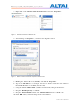
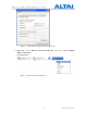
TPS10-013_rev1.2_A2N_Configuration_Manual_-_fm_1.0.1._FCC.doc 3. Right-click on the “Wireless Network Connection” and select “Properties”. Figure 2 Network Connections in Windows XP 4. After clicking on “Properties”, you will see the diagram as below. Figure 3 Wireless Network Connection Properties in Windows XP 5. Marking the “Internet Protocol (TCP/IP)” and click the “Properties”. 6. Type in an “IP address”, for example, 192.168.1.
TPS10-013_rev1.2_A2N_Configuration_Manual_-_fm_1.0.1._FCC.doc Figure 4 Internet Protocol (TCP/IP) Properties in Windows XP 11. Right-click on the “Wireless Network Connection” and select “View Available Wireless Networks”.
TPS10-013_rev1.2_A2N_Configuration_Manual_-_fm_1.0.1._FCC.doc 12. Click on the “Altai Wireless Network” Figure 6 Showing Available Wireless Network Connections in Windows XP 3.2 CHECK ACCESS “ping” utility of DOS mode is a handy tool to check the access to the A2 WiFi. 1. Go to DOS mode by typing “cmd” in “Run”. 2. Type command: ping 192.168.1.20 The A2 WiFi shall respond to your ping request if it has a correct connection with your PC.
TPS10-013_rev1.2_A2N_Configuration_Manual_-_fm_1.0.1._FCC.doc 4 CONFIGURATION WITH WEB-ADMIN 4.1 WEB BROWSER CONNECTION The A2 can be accessed through a Web Browser, for example, Internet Explorer (IE). 1. Open an IE session and type the IP address of the A2 Pico AP. Example: https://192.168.1.20, where 192.168.1.20 is the A2’s IP address. The A2 default IP Address is 192.168.1.20. Note: the release version 1.0.0. only supports https format URL link. 2. A window will pop up, as shown in Figure 5.
TPS10-013_rev1.2_A2N_Configuration_Manual_-_fm_1.0.1._FCC.doc 3. Figure 6 Figure 6. A Menu Bar is located on the left hand side of the IE window. Different configurations can be chosen through the menu bar.
TPS10-013_rev1.2_A2N_Configuration_Manual_-_fm_1.0.1._FCC.doc 4.2 CHECKING THE A2 VERSIONS The running version can be checked by selecting About under Administration in the menu bar. In Figure 7, it shows: Firmware Version: v1.0.0 or above versions Figure 7 4.
TPS10-013_rev1.2_A2N_Configuration_Manual_-_fm_1.0.1._FCC.doc The User Name and Password for login are mentioned in Section 4.1, but only password can be changed by entering a new string in the field of Password. Note: it is need to re-enter to confirm the password. Please press Change Password button to store the new password. The System Name is the name of the A2 WiFi. NOTE: Click the Update icon to store the changed settings. 4.
TPS10-013_rev1.2_A2N_Configuration_Manual_-_fm_1.0.1._FCC.doc address. It also supports SNMP Manager Access Control List which allows user to configure a list of allowed SNMP manager IPs for managing the A2. When the SNMP manger ACL mode is enabled, only SNMP request generated from the any of configured SNMP manger on the ACL will be handled. NOTE: Click the Update icon to store the changed settings. 4.
TPS10-013_rev1.2_A2N_Configuration_Manual_-_fm_1.0.1._FCC.doc 4.8 SWITCH MODE 4.8.1 Static IP address In IP Assignation, there are two kinds of working mode for A2 base station: Static IP address and DHCP Client. In Switch mode, by clicking Network Configuration in the System page, users can configure the IP Address, Subnet Mask and Gateway Address, as shown in Figure 10 and Figure 11.
TPS10-013_rev1.2_A2N_Configuration_Manual_-_fm_1.0.1._FCC.doc 4.8.2 VLAN Configuration Default setting of VLAN is “Disabled”. By clicking “Enabled”, VLAN can be enabled. A2 supports VLAN to VAP mappings to provide network security. Management VLAN is used to configure the management VLAN of A2. A2 can only be accessed through the specified management VLAN when VLAN is enabled. It will be ignored when VLAN is disabled. Native VLAN Tagging control is used to control the untagged packet when VLAN is enabled.
TPS10-013_rev1.2_A2N_Configuration_Manual_-_fm_1.0.1._FCC.doc NOTE: DNS Auto Update can only be enabled when DHCP client is enabled. If the DNS Auto Update is enabled, it must be used in conjugation with either the DHCP Client or the PPPoE Mode being enabled. If both the DHCP Client and the PPPoE Mode are disabled then the DNS Auto Update must also be set to Disabled. 4.9 GATEWAY MODE In Gateway mode, by clicking Network Configuration in the System page, users can configure the WAN and LAN settings.
TPS10-013_rev1.2_A2N_Configuration_Manual_-_fm_1.0.1._FCC.doc 4.9.1.2 PPPoE Configuration If PPPoE is chosen, a PPPoE login will be attempted for the PPPoE Username, PPPoE Password and PPPoE Service Name, see Figure 13. Figure 13 PPPoE Configuration NOTE: The DNS Auto Update should be set to Disable when using PPPoE. User need to configure the DNS server IP address manually. PPPoE Active Mode, Max Idle Time and Redial Period can be configured.
TPS10-013_rev1.2_A2N_Configuration_Manual_-_fm_1.0.1._FCC.doc 4.9.2 LAN Configuration In Gateway Mode, the A2 can be a DHCP server, a DHCP relay or none of them. When the DHCP Server Mode sets to Server, the A2 will act as a DHCP server and use the settings specified in the field Start IP Address, Maximum Number of DHCP Users and DNS to serve the wireless clients. 1. Configure the Local IP Address and Subnet Mask Length. Local IP Address is the gateway IP address for the client who associates A2 WiFi.
TPS10-013_rev1.2_A2N_Configuration_Manual_-_fm_1.0.1._FCC.doc Figure 15 Configure DHCP Server Disable 4.10 ACCESS LINK SAFE MODE/ BACKHAUL LINK SELF-HEALING Access Link Safe Mode is for detecting the backhaul link integrity. If the AP loses its backhaul connectivity, it forces the clients to re-associate with another AP by changing its SSID to a default “A2 Safe Mode XXX”, where “XXX” is the MAC address of the 2.4GHz radio in hexadecimal.
TPS10-013_rev1.2_A2N_Configuration_Manual_-_fm_1.0.1._FCC.doc 4.11 SETUP – WIRELESS RADIO PARAMETER Wireless radio parameters can be modified under Configuration in the menu bar. By selecting the icons, 2.4G Radio can operate on different modes separately: AP mode, Repeater mode, Bridge mode and Disable. The default setting of 2.4G Radio is AP mode. 4.12 AP MODE Wireless Radio working on AP mode is used for clients association. Altai A2 WiFi combine 802.11b/g and draft 802.
TPS10-013_rev1.2_A2N_Configuration_Manual_-_fm_1.0.1._FCC.doc 4.12.2 Auto Channel Selection By default, the Auto Channel Selection is disabled; the A2 is fixed on Channel 6. When Enabled of Auto Channel Selection is chosen, A2 WiFi can scan all available radio channels which are assigned to the regulatory domain. The “cleanest” channel is then selected as the operating channel. NOTE: After changing frequency channel, it takes around 3 minutes for A2 to optimize its radio performance. 4.12.
TPS10-013_rev1.2_A2N_Configuration_Manual_-_fm_1.0.1._FCC.doc Table 3 Beacon Interval Fragment Threshold: It means the size of each frame. If it is set to 256 bytes and the size of data block is 1024 bytes, the data block will be divided to four frames to send. RTS/CTS Threshold: RTS is a flow control mechanism to prevent collision between 802.11b and 802.11g mobile stations to send data to the access point in the same time.
TPS10-013_rev1.2_A2N_Configuration_Manual_-_fm_1.0.1._FCC.doc Figure 18 VAP Setting 4.12.7 Access Control List (ACL) By selecting Access Configurations, a window, as shown in Figure 19, is brought up for choosing the ACL mode, adding MAC Address with ACL Type (Allow or Deny). There are three modes in the Access Control List (ACL). They are Disabled, Enabled-Allow and Strict-Deny: 1. Disabled - The function of ACL is disabled. 2. Enabled–Allow - The function of ACL is enabled.
TPS10-013_rev1.2_A2N_Configuration_Manual_-_fm_1.0.1._FCC.doc Figure 19 ACL 4.12.8 Encryption and Authentication By selecting Security Configurations, a window, as shown in Figure 20, is brought up for choosing the Authentication Mode and Cipher Mode.
TPS10-013_rev1.2_A2N_Configuration_Manual_-_fm_1.0.1._FCC.doc After selecting Open or Shared-Key for Authentication Mode, WEP for Cipher Mode, the WEP key settings can be defined as shown in Figure 21. WPA/WPA2 or WPA-PSK/WPA2-PSK can be enabled by selecting WPA/WPA2 or WPA-PSK/WPA2-PSK for Authentication Mode. The AES and TKIP are the two available options for Cipher Mode. The related settings are shown in Figure 20 and Figure 23. NOTE: Click the Update icon to store the WEP or WPA settings.
TPS10-013_rev1.2_A2N_Configuration_Manual_-_fm_1.0.1._FCC.doc RADIUS server is used for authentication. A2 WiFi can store separate RADIUS server address for each VAP. It is only visible when the Authentication Mode is set to “WPA”. The default setting of RADIUS server port is 1812. RADIUS secret shared password between the RADIUS server and A2 WiFi. A password up to 128 characters long can be added.
TPS10-013_rev1.2_A2N_Configuration_Manual_-_fm_1.0.1._FCC.doc 4.13 REPEATER MODE Under Wireless Radio web-site interface, Station mode can be chosen. By clicking Station icon, backhaul link can be established through associating the Station VAP with the remote APs. That means the Wireless Radio works as backhaul link, clients can associate with other VAPs who works under AP mode.
TPS10-013_rev1.2_A2N_Configuration_Manual_-_fm_1.0.1._FCC.doc 4.14 BRIDGE MODE The 5GHz Radio, Regulatory Domain, Wireless Mode, Radio Frequency (Channel), Transmit Power, Encryption Configuration, Advanced Settings and Remote Bridge Configuration can be configured by selecting 5GHz Radio under Configuration in the menu bar, as shown in Figure 25. Figure 25 5GHz Radio Parameter Configuration 4.14.1 Bridge Radio Wireless Mode A2 WiFi can work under either 802.11a mode or 802.
TPS10-013_rev1.2_A2N_Configuration_Manual_-_fm_1.0.1._FCC.doc In 802.11a mode: User can select a 5GHz channel in the pool from channel 149 to 165 (5.745GHz to 5.825GHz). In 802.11na HT20: Users can select a 5GHz channel in the pool from channel 149 to 165 (5.745GHz to 5.825GHz). In 802.11na HT40ext ch+1: Users can select a 5GHz channel in the pool from channel 151 (5.755GHz). In 802.11na HT40ext ch-1: Users can select a 5GHz channel in the pool from channel 159 (5.795GHz). 4.14.
TPS10-013_rev1.2_A2N_Configuration_Manual_-_fm_1.0.1._FCC.doc RTS/CTS Threshold: RTS is a flow control mechanism to prevent collision between 802.11b and 802.11g mobile stations to send data to the access point in the same time. CTS is another flow control mechanism to prevent collision when two mobile stations, who do not know the existence of each other, send data to the access point in the same time.
TPS10-013_rev1.2_A2N_Configuration_Manual_-_fm_1.0.1._FCC.
TPS10-013_rev1.2_A2N_Configuration_Manual_-_fm_1.0.1._FCC.doc 4.15 DISABLE MODE The particular radio of A2 WiFi can be disabled by click the Disable icon. There is no need to configure the Transmit Power and Advanced Settings. Figure 29 Wireless Radio Disable Mode 4.16 REBOOT System reboot of A2 WiFi can be chosen by selecting Reboot under Administration in the menu bar. It is required to select Reboot Base Station to confirm this action, as shown in Figure 30.
TPS10-013_rev1.2_A2N_Configuration_Manual_-_fm_1.0.1._FCC.
TPS10-013_rev1.2_A2N_Configuration_Manual_-_fm_1.0.1._FCC.doc 4.17 RESTORE CONFIGURATION TO DEFAULT SETTING The choices of factory default can be chosen by selecting Factory Default under Administrations in the menu bar. The default settings (IP Address, Subnet Mask, Default Gateway Address and Remote Bridge Configurations are retained) can be restored by selecting the icon Reset to Factory Default (address retained) or Reset to Factory Default, as shown in Figure . Please reboot the A2 WiFi afterwards.
TPS10-013_rev1.2_A2N_Configuration_Manual_-_fm_1.0.1._FCC.doc 5 PERFORMANCE MANAGEMENT MONITORING IN WEB-ADMIN 5.1 SYSTEM The statistics can be monitored by selecting System under Status in the menu bar. All details are shown on the window, as shown in Figure . Figure 33 Details of the system The status of each VAP can be shown by clicking Vap under the field of Wireless Radio, as shown in Figure .
TPS10-013_rev1.2_A2N_Configuration_Manual_-_fm_1.0.1._FCC.doc The status and MAC address of each remote bridge can be shown by selecting Remote Bridge under the field of 5GHz Radio, as shown in Figure . Figure 35 5.2 Statuses of the Remote Bridges CLIENTS STATISTICS The clients association statistics can be monitored by selecting Clients Statistics under the field of Status in the menu bar, as shown in Figure . The Address Lease Table shows the Client MAC Address, Client IP Address of each end user.
TPS10-013_rev1.2_A2N_Configuration_Manual_-_fm_1.0.1._FCC.doc 5.3 RADIO ASSOCIATION-AP MODE The each radio association statistics can be monitored by selecting Radio Association under the field of Status in the menu bar, as shown in Figure . The corresponding statistics can be shown by selecting the related MAC Address, as shown in Figure 38. The Association Table shows the ID, Mac Address, RSSI, and VAP of each station as shown in Figure . A more detailed 2.
TPS10-013_rev1.2_A2N_Configuration_Manual_-_fm_1.0.1._FCC.doc Figure 38 5.4 Radio Statistics per MAC Address (data is cumulative) RADIO ASSOCIATION-REPEATER MODE The association status of radio working on repeater mode can be monitored by selecting Radio Association under the field of Status in the menu bar, as shown in Figure 39 and Figure 40.
TPS10-013_rev1.2_A2N_Configuration_Manual_-_fm_1.0.1._FCC.doc Figure 40 5.5 Association AP Statistics per MAC Address (data is cumulative) RADIO ASSOCIATION-BRIDGE MODE The bridge radio association can be monitored by selecting Radio Association under the field of Status in the menu bar, as shown in Figure 41 and Figure 42.
TPS10-013_rev1.2_A2N_Configuration_Manual_-_fm_1.0.1._FCC.
TPS10-013_rev1.2_A2N_Configuration_Manual_-_fm_1.0.1._FCC.doc 6 SOFTWARE UPGRADE THROUGH WEB-ADMIN The firmware can be upgraded by selecting Firmware Update under the field of Administrations in the menu bar respectively. Please note that the connection link should be maintained during file transfer to prevent interruption to the system. 6.1 FIRMWARE UPDATE THROUGH HTTP OR HTTPS Follow the steps below to perform the Firmware Update with a firmware image file (.
TPS10-013_rev1.2_A2N_Configuration_Manual_-_fm_1.0.1._FCC.
TPS10-013_rev1.2_A2N_Configuration_Manual_-_fm_1.0.1._FCC.doc 7 GLOSSARY 802.1q IEEE 802.1Q was a project in the IEEE 802 standards process to develop a mechanism to allow multiple bridged networks to transparently share the same physical network link without leakage of information between networks (i.e. trunking). IEEE 802.1Q is also the name of the standard issued by this process, and in common usage the name of the encapsulation protocol used to implement this mechanism over Ethernet networks.
TPS10-013_rev1.2_A2N_Configuration_Manual_-_fm_1.0.1._FCC.doc ad-hoc mode An 802.11 networking framework in which devices or stations communicate directly with each other, without the use of an Access Point (AP). Ad-hoc mode is also referred to as peer-to-peer mode or an Independent Basic Service Set (IBSS). Ad-hoc mode is useful for establishing a network where wireless infrastructure does not exist or where services are not required.
TPS10-013_rev1.2_A2N_Configuration_Manual_-_fm_1.0.1._FCC.doc DSSS Direct Sequence Spread Spectrum: One of two types of spread spectrum radio technology used in wireless LAN (WLAN) transmissions. To increase a data signal's resistance to interference, the signal at the sending station is combined with a higher-rate bit sequence that spreads the user data in frequency by a factor equal to the spreading ratio.
TPS10-013_rev1.2_A2N_Configuration_Manual_-_fm_1.0.1._FCC.doc special-purpose device that performs an application-layer conversion of information from one protocol stack to another. handoff The process of transferring the handling of that cellular call to the new base station. host address Logical address configured by an administrator or server on a device. Logically identifies this device on an internetwork.
TPS10-013_rev1.2_A2N_Configuration_Manual_-_fm_1.0.1._FCC.doc (BIA) of the local LAN interface. Variously called “hardware address”, “physical address”, “burned-in address” or “MAC-layer address”. MTU Maximum Transmission Unit: The largest packet size, measured in bytes, that an interface can handle.
TPS10-013_rev1.2_A2N_Configuration_Manual_-_fm_1.0.1._FCC.doc required secret, shared key is presumed to have been delivered to participating STAs via a secure channel that is independent of IEEE 802.11. During the shared key authentication exchange, both the challenge and the encrypted challenge are transmitted. This facilitates unauthorized discovery of the pseudorandom number (PRN) sequence for the key/IV pair used for the exchange.
TPS10-013_rev1.2_A2N_Configuration_Manual_-_fm_1.0.1._FCC.doc WEP Wired Equivalent Privacy: A security protocol for wireless local area networks (WLANs) defined in the 802.11b standard. WEP is designed to provide the same level of security as that of a wired LAN. LANs are inherently more secure than WLANs because LANs are somewhat protected by the physicalities of their structure, having some or all part of the network inside a building that can be protected from unauthorized access.