Measure what you see.
BYK-mac ROBOTIC Manual Patent pending BYK-Gardner GmbH Lausitzer Str. 8 D-82538 Geretsried Germany Tel. 0-800-gardner (0-800-4273637) +49-8171-3493-0 Fax +49-8171-3493-140 281 021 572 1002 BYK - Gardner USA 9104 Guilford Road Columbia, MD 21046 USA Phone 800-343-7721 301-483-6500 Fax 800-394-8215 301-483-6555 www.byk.
Dear customer, thank you for having decided for a BYK-Gardner product. BYK-Gardner is committed to providing you with quality products and services. We offer complete system solutions to solve your problems in areas of color, appearance and physical properties. As the basis of our worldwide business, we strongly believe in total customer satisfaction.
Table of content Inhaltsverzeichnis 1. Safety instructions ................................................................................ 5 2. System description and delivery notes ............................................ 10 3. Mounting and Manual Measurements .............................................. 11 3.1 Mountig of instrument ............................................................................ 11 3.2 Mounting of standards ......................................................
4
Safety instructions 1. Safety instructions • Before operating the instrument the first time, please read the operating instructions and take particular notice of the safety instructions. • If you use the unit and accessories properly, there are no hazards to fear. • This product is equipped with safety features. Nevertheless, read the safety warnings carefully and use the product only as described in these instructions to avoid accidental injury or damage.
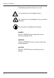
Safety instructions The following symbols and terms are used. This symbol warns of the danger of injury. This symbol warns of the danger of injury caused by electricity. This sign points out additional information. DANGER The term DANGER warns of possible severe injuries and danger to life. WARNING The term WARNING warns of injuries and severe material damage. CAUTION The term CAUTION warns of slight injuries or damage.
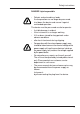
Safety instructions DANGER injuries possible • Defects and extraordinary loads If safe operation can no longer be presumed, shut down the device and secure it against unintended operation. The device must be presumed unsafe to operate: • if visible damage is evident • if the instrument is no longer working • if it has been stored for long periods under adverse conditions • after harsh treatment during shipping.
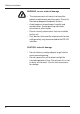
Safety instructions WARNING severe material damage • • • • The measurement unit consists of sensitive optical and electronic precision parts. Prevent it from being dropped, bumped or shaken! Avoid exposure to continuous humidity and condensation. Avoid splashing with water, chemicals or other liquids. Please use only accessories that are available for the unit. Only devices that meet the requirements for lowvoltage safety may be connected to the RS 422 interface.
Safety instructions • • Avoid prolonged high relative humidity and do not allow condensation water. Do not use any acetone for cleaning the unit! The unit housing is resistant to many solvents. For cleaning you should use a soft, moist cloth. Excessive dirt and dust can be removed with ethanol or cleaning alcohol.
System description and Delivery notes 2. System description and Delivery notes BYK-mac ROBOTIC measures color traditionally at five aspecular angles (15°/25°/45°/75°/110°) with a 45° illumination. Additional color measurement ”behind” the gloss for color travel of interference pigments is implemented at -15°. To simulate sparkle under direct sunlight additional illuminations are used at 15° /45° and 75°. Diffused illumination for graininess evaluation is created by using a BaSO4 coated sphere.
Mounting and Manual Measurements 3. Mounting and Manual Measurements Before operating the instrument for the first time, please read the operating manual and take particular notice of the Safety Instructions. 3.1 Mountig of instrument The measuring instrument is fixed on the mounting board with three screws (arrow). The millings on the fixing bar and a nib ensure proper attachment. A drawing, that contains all dimensions for producing the mounting board, is enclosed with each instrument.
Mounting and Manual Measurements 3.2 Mounting of standards The instrument is supplied with a white calibration standard and a cyan and effect checking reference. The standards are to be installed perpendicularly in order to avoid getting dirty. Please make sure that the four round rubber-bonded metal attachments are in place on the backside. These attachments provide the necessary elasticity when putting the instrument on the standards.
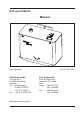
Power supply 4 Power supply LED2 LED1 1 2 The instrument is supplied by an external AC power adapter. Power supply and data transmission are combined in a 9-pole sub D plug. In order to connect the measuring instrument, first check the wiring and the matching of the power supply. Then plug in the emergency stop plug (1). Subsequently plug in the sub D plug (2), and switch on power. The light-emitting-diode LED1 signals the connected power supply.
Emergency stop 5 Emergency stop The instrument is equipped with an emergency stop system. To ensure proper functionality it is important that the bottom plate of the instrument is pressed in not more than 9 mm from the zero position. If during a malfunctioning the instrument is pressed too strongly against the surface, the instrument recognizes this and cuts off the robot.
Interface 6 Interface Power Supply and Communication Pin Robotic SUBD9pin Male PC or RS422 Converter Signal Signal LED 1 LED 2 Pin 6 Pin 5 Pin 9 Pin 1 Pin 6 Pin 1 Pin 3 Emergency stop LED 2 LED 1 Pin 9 1 RxD+ (B) TxD+ (B) 2 RxD- (A) TxD- (A) Pin 1 3 TxD+ (B) RxD+ (B) 4 TxD- (A) RxD- (A) GND [*] GND [*] Pin 5 5 6 U_in 7 GND 8 U_in 9 GND [*] optional: U_in at Pin 6,8 and GND at Pin 7,9 for power supply.
Calibrate 7 Calibrating the instrument 7.1 Calibration Information Standards The instrument is supplied with a white calibration standard and a cyan and effect checking reference. Black calibration is done internally by the instrument. Mount the test tiles at the position intended for the instrument test. White standard Cyan and effect reference 16 Cyan and effect check are recommended to be done every day. White calibration must be accomplished at least every month.
Calibrate 7.2 Calibration Notes • • • The standards should be cleaned periodically. For cleaning procedure see section "Cleaning and Maintenance“. Please make sure that the standards are not scratched. Do not move the instrument while taking a calibration measurement. If motion is detected, an error message will be displayed and calibration is aborted. When moving from cold to warm environment, there is a danger of condensation.
Standards 8 Standards DIN 5033 Colorimetry; basic concepts. DIN 5036 Radiometric and photometric properties of materials; definitions characteristic. DIN 6174 Colorimetric evaluation of colour differences of surface colours according to the CIELAB formula. DIN 6175-2 Tolerances for automotive paints Part 2: Goniochromatic paints ISO 7724 Paints and varnishes - Colorimetry ASTM D 2244 Standard Test Method for Calculation of Color Differences From Instrumentally Measured Color Coordinates.
Technical Data 9 Technical Data Color Measuring Geometry Measuring Area Spectral Range Measurement Range Repeatability¹ Reproducibility¹ Color Scales Illuminants Observer Illumination 45°, -15°,15°, 25°, 45°, 75°, 110° aspecular viewing 87 x 23 mm 400 - 700 nm, 10 nm resolution 0 to 400 % reflectance 0.02 dE* 10 consecutive readings on white tile 0.
Cleaning and Maintenance 10 Cleaning and Maintenance • • • • Before cleaning, the instrument and accessories must be disconnected from the power supply as described in the safety instructions. Do not insert any objects into the measurement aperture for cleaning. The instrument could get damaged. Do not use any acetone for cleaning the unit! The instrument housing is resistant to a number of solvents, but cannot be guaranteed to withstand all chemicals.
Cleaning and Maintenance 10.2 Light protection cover The measurement aperture of the instrument is surrounded by a light protection cover made out of rubber. It acts as a protection against ambient light. Keep the cover always clean and exchange it when beeing dirty or damaged.
Service and Certification 11 Service and Certification Service Besides the repair of your instrument we offer the following additional services: First diagnosis on the telephone or by e-mail Call us or send us an e-mail and we will try to solve your problem. If this is not successful, please send us the instrument for repair. Preventive maintenance, calibration and recertification For precautionary reasons we recommend regular preventive maintenance.
Service and Certification Service Centers for BYK-Gardner products Germany BYK-Gardner GmbH Lausitzer Strasse 8 82538 Geretsried Germany Phone:+49-8171-3493-0 Fax: +49-8171-3493-166 USA BYK-Gardner USA 9104 Guilford Road Columbia, MD 21046 USA Phone:+1-301-483-6500 Fax: +1-301-483-6555 China BYK-Gardner Shanghai Office 3/F, Building 22 No. 140 Tianlin Road Xuhui District Shanghai 200233 P.R.
Copyright 12 Copyright This instruction manual is an important part of this instrument. It contains essential information about setting up, placing in service and use. If you pass the device on to another user, please ensure that the instruction manual is included with the instrument. The manual must be studied carefully before working with the equipment. Please contact your regional service office if you have any questions or require additional information about the device.
281 021 572 E 1002