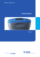
Measure what you see.
cloud-runner Manual Patent pending BYK-Gardner GmbH Lausitzer Str. 8 D-82538 Geretsried Germany Tel. 0-800-gardner (0-800-4273637) +49-8171-3493-0 Fax +49-8171-3493-140 270 021 236 E 1010 BYK - Gardner USA 9104 Guilford Road Columbia, MD 21046 USA Phone800-343-7721 301-483-6500 Fax 800-394-8215 301-483-6555 www.byk.
Dear customer, thank you for having decided for a BYK-Gardner product. BYK-Gardner is committed to providing you with quality products and services. We offer complete system solutions to solve your problems in areas of gloss and physical properties. As the basis of our worldwide business, we strongly believe in total customer satisfaction.
Table of contents Table of contents 1. Safety instructions ............................................................................. 5 2. System description and Delivery notes ........................................... 11 Storage structure ................................................................................................ 11 3. Power supply .................................................................................... 14 3.1 Rechargeable battery pack ..........................
Table of contents 10. Advanced Configuration .................................................................... 36 10.1 Interrupt ....................................................................................................... 36 10.2 Input Parameter 2, 3 and Comment ......................................................... 36 10.3 Input ID ......................................................................................................... 36 10.4 Input Checkzone ..............................
Safety instructions 1. Safety instructions • Before operating the instrument the first time, please read the operating instructions and take particular notice of the safety instructions. • If you use the unit and accessories properly, there are no hazards to fear. • This product is equipped with safety features. Nevertheless, read the safety warnings carefully and use the product only as described in these instructions to avoid accidental injury or damage.
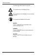
Safety instructions The following symbols and terms are used. This symbol warns of the danger of injury. This symbol warns of the danger of injury caused by electricity. This sign points out additional information. DANGER The term DANGER warns of possible severe injuries and danger to life. WARNING The term WARNING warns of injuries and severe material damage. CAUTION The term CAUTION warns of slight injuries or damage.
Safety instructions DANGER injuries possible • Defects and extraordinary loads If safe operation can no longer be presumed, shut down the device and secure it against unintended operation. The device must be presumed unsafe to operate: • if visible damage is evident • if the instrument is no longer working • if it has been stored for long periods under adverse conditions • after harsh treatment during shipping.
Safety instructions • When working with the batteries make certain there is no short circuit on the contacts. Metallic objects must not come in contact with the bare contacts. WARNING severe material damage • • • • 8 The measurement unit consists of sensitive optical and electronic precision parts. Prevent it from being dropped, bumped or shaken! Avoid exposure to continuous humidity and condensation. Avoid splashing with water, chemicals or other liquids.
Safety instructions CAUTION material damage • • • • • Do not allow any foreign objects to get into the measurement opening. Do not expose the unit to direct sunlight for extended periods of time. Do not store it in a hot or dusty environment. Use the instrument case for storage. Rechargeable Li-Ion battery packs: Do not charge at temperatures below 0°C. The allowable discharge temperature range is -20 to +60°C. Please refer to the charging instructions in section „Power Supply“.
System description and Delivery notes 2. System description and Delivery notes Please read the instruction manual before using the instrument and note the safety instructions. The instrument simulates visual evaluation under different observing angles and characterizes clouds / mottles by their size and visibility. The measurement system consists of the portable measurement device, docking station and the smart-chart program.
System description and Delivery notes The saved results are transferred to the PC and displayed as a QC report. The data is saved in a database for further analysis over time. Pre-prepared test reports in the smartchart software assist in analyzing the data. Storage structure Each measurement series contains a header and the individual measurements with name (test zone) and measured values. In the header, up to 5 parameters can be defined for object identification.
System description and Delivery notes Application hints: Measurement task Recommendation 1. Single measurements, e.g. occasional sample-measurements - Menu “Measure“ > “MEMORY“. Transfer results to smart-chart. 2. Objects with several test zones. Test sequence / identifikation can be standardized, e.g. automobile or addon parts - Generate Organizer in smartchart and transfer it to the instrument. Take readings, see chapter 8.3. Transfer results to smart-chart and store in data base.
System description and Delivery notes cloud-runner AM-6350 Comes complete with: Mottling meter with protective cover, Reference tile with certificate, smart-chart software on CD, Docking station with USB cable, 2 rechargeable LiIon battery packs, Operating manual, Carrying case.
Power supply 3. Power supply Rechargeable battery pack Before operating the instrument for the first time, please read the operating manual and take particular notice of the Safety Instructions. Unpack the instrument and check the delivery for completeness (See chapter “Delivery Notes”). Powering the instrument The measurement unit is operated with the rechargeable battery pack included with delivery. 3.
Power supply 3.2 Docking station power supply Power is supplied to the docking station through the external power supply unit. Connect the external power supply unit to the docking station. Connect the appropriate end of the power connection line to the power supply unit and the plug end of the power connection line to the power outlet after verifying that the specifications of the power supply unit match the power source in terms of current and voltage. 3.
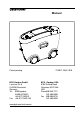
Controls 4. Controls 2 3 1 4 7 5 6 Measurement unit 1 2 3 4 5 6 7 16 Mode scroll wheel: Menu selection Display for user guidance and measurement values Signal lamp Operate button: Turn on, measurement and confirmation of menu items.
Controls The basic system consists of the measurement device and the docking station. The docking station is used to exchange data and to charge the rechargeable battery pack. When the unit is not in use, place it in the docking station. In this way the rechargeable battery pack will be charged and the instrument will always be ready for measurements. The operate button and scroll wheel are used to control the system. Pressing “operate“ turns the unit on and causes a menu to be displayed.
Getting started 5. Getting started 5.1 Turning the unit on and measuring Turn the instrument on by pressing the operate button. If the operate button is depressed while switching the unit on, a reference to the firmware appears along with the date of the last certification. The unit then switches to the last measurement mode to be selected. If no measurement mode has been previously selected, the main menu appears. For the first steps, select MEMORY under the “Measure” menu.
Getting started After completing a measurement, a signal is heard and the measurement results are displayed. Performing the measurement requires some practice. The following error messages are especially likely to occur during the first trials. A warning signal is heard and the light diode flashes at a rapid rate. At the same time, a message appears in the display indicating the type of error: Speed You have moved the measurement unit too quickly or unevenly over the sample.
Getting started 5.2 Display of measurement results A C B The measurement results displayed will vary depending on the options selected in the Configuration (see chapter 9, 10). Displayed results may be broken down into the following elements: A: Name of the measured sample or checkzone. B: The number of performed and predefined measurements (e.g. 2 of 3). The statistic function is activate if the predefined number of measurements is greater than 1.
Testing the instrument 6. Testing the instrument Due to the measurement principle, calibration of the equipment is not necessary. It is recommended, however, to check the functionality of the instrument at regular intervals (about once every 3 months). The reference tile included with delivery is provided for this purpose. Select the “Standard” in the Measure menu. The configuration of this organizer is fixed and cannot be changed. The unit then switches to the measurement mode.
Menu operation 7. Menu operation 7.1 Navigation All functions are controlled by the mode scroll wheel and the operate button. Pressing the operate button or the scroll wheel causes a menu to appear in the display. Turning the wheel allows you to move the cursor to the desired function. Select or activate the function by pressing the operate button.
Menu operation 7.2 Overview of main menu Measure MEMORY MY MEMORY Standard My Model Default memory for single measurements User-defined memory (appears only if generated under “Memory” menu) To verify the device function on the test panel Measurement with Organizer (appears only if loaded from PC) Memory Config. New Config. Change Config.
Menu operation 7.3 Changing names and numbers For some functions, you can enter or change the date or name. The triangle pointing upward marks the item that can be changed. To change the character, turn the scroll wheel. When you press the scroll wheel, the arrow jumps to the next character. After you have adjusted the last character, confirm your input by pressing the operate key. A confirmation message appears which allows you to save the settings or change incorrect entries.
Measure 8. Measure 8.1 Measure For beginning a new test series, select Measure from the Main Menu. The Measure menu offers a list of names to identify the new test series (Parameter1). Individual entries can be added to the list. Two types of test procedures can be differenciated by a symbol in front of the names: Memories: generated in the instrument, allow to input identification parameters during measurement procedure.
Measure To exit a measurement series, press the scroll wheel. A menu appears for deleting, interrupt and ending the series: Delete Last Deletes the last measurement within a checkzone.There is no additional warning before the deletion. Delete Checkzone Deletes the entire last checkzone. There is no additional warning before the deletion. Delete Test Series Deletes the entire measurement series. A confirmation display appears before final deletion.
Measure Interrupt Checkzone This function allows you to exit a checkzone/sample before reaching the preset number of measurements or to skip a checkzone. Then you can continue the measurement series with the next checkzone. If Interrupt is not activated in the Configuration menu (Chapt. 9) or the Configuration of the selected Organizer, a message will be displayed. Parameter Info Gives you an information about the selected parameters of the sample. End Test Series Ends the entire measurement series.
Measure 8.2 MEMORY This is a memory with default settings for single measurements on samples. The settings can be changed for individual needs, e.g. scale selection, statistics or scan length. For further information please refer to chapter “Configuration”. Changes in the configuration are only possible if no measurement data are saved under the desired memory name. Before you change the configuration, first backup the stored data and then delete them.
Measure 8.3 Organizer An organizer file defines a test sequence for user guidance, e. g. for measuring a car body with several checkzones. These files can be generated with the smart-chart software. If no Organizer is loaded in the device, one must be transferred from a PC. Once an Organizer is selected, a menu appears for Parameter 2 of the Organizer. Colors are listed as an example of this in the menu to the side. After you have selected the appropriate color, a selection menu appears for Parameter 3.
Measure The name of the checkzone to be measured first, appears on the left side of the display. The number of performed and predefined measurements (e.g. 2 of 3) appear in the upper right corner. Once the number of measurements for the checkzone is reached, a double audio signal is heard. The display shows the results of the measurement and indicates that the measurement of the checkzone is complete (e.g.3/3). Pressing briefly the operate button allows the next checkzone to appear in the display.
Measure 8.4 Memory with Parameter Input By using the internal memory function of the instrument, measurement series and samples/ checkzones can be identified by individual names during the test procedure. Therefore, input options of the menu item Advanced Configuration need to be activated for the desired memory. You can use the existing MEMORY in the instrument or create another memory name (Parameter 1). For more information about change of configuration please refer to section Configuration.
Measure Once you have reached the preset number of measurements (n = ...), you might be prompted to enter a name for the checkzone (“Input Checkzone” aktivated). Proceed by entering the name of the checkzone as described above for the parameters. If “Input Checkzone” is deactivated, the instrument automatically assigns the name SAMPLE 01 and then increments this name. To exit the test series, presss the scroll wheel and activate End Test Series.
Configuration 9 Configuration For every memory, specific settings can be made that affect the test procedure and the evaluation of the data.These settings are individually definable in the Memory menu: Config New for a new memory Config Change for an existing memory Once a memory is selected, the menu with the various configuration items appears. The complete contents of the menu are shown in the neighboring illustration. The current settings are displayed on the right side next to the black triangles.
Configuration 9.1 Number of Measurements This function allows selection of the numbers of readings to be taken per sample. If the number is greater than 1, the measurements are statistically evaluated. Turning the scroll wheel adjusts the number while pressing it shifts the decimal place one further over. Pressing operate completes the process and a confirmation display appears. 9.2 Scanlength The scanlength is adjustable between 10 and 100 cm in 1 cm steps to your individual needs.
Configuration 9.4 Scales Eight scales may be selected for the display of the measurement results. Following scales are available: Mottle Spectrum: Md...Mi The measurement signal is filtered into 6 different ranges, which represent a specific range of mottle sizes. Mottle Chart: T, M a two-dimensional evaluation of small and large mottles. Texture: a measure for mottles smaller ~ 25mm Mottling: a measure for mottles larger ~ 25mm Select the desired scale and press the operate button.
Advanced Configuration 10. Advanced Configuration 10.1 Interrupt If statistic is activated in the configuration of the selected memory (n > 1), you can interrupt a checkzone (sample) before reaching the preset number of measurements. 10.2 Input Parameter 2, 3 and Comment When active, these parameters allow to assign individual names for identification of a new test series. 10.3 Input ID When this function is active, you can enter an identification code e.g. vehicle ID number for each new test series. 10.
Memory 11. Memory In the Memory menu you can create new memories with a configuration according to specific needs (e.g. scales, statistics). Also, the configuration of existing memories can be changed. Memories which are no longer needed, will be deleted with the function “Config Delete”. Additionally, the menu allows to recall or delete a measured test series. 11.1 Configuration New After selecting this menu item, you will be prompted to enter a name for the new Memory (Parameter 1).
Memory 11.2 Configuration Change This function allows to modify the configuration of an existing memory. A menu appears with a list of the existing memories and organizers. Select the desired memory. A menu then appears listing the configuration of the selected memory. To change the settings, refer to chapter 9 and 10. To exit the menu, activate the arrow at the top of the menu. Note: Changes to the settings of Organizer files are not permitted. If an Organizer is selected, a warning message will appear.
Memory 11.4 Data View You can use this function to display all measurement series stored in the instrument. First, the selection menu for existing memories will be shown. Select the desired memory to recall its contents. If the selected memory is identified by additional parameters, further menus will appear: Select Parameter 2. Select Parameter 3. As appropriate, select Comment and ID accordingly. Finally, select the measurement series itself under date and time.
Memory 11.5 Data Delete This function deletes a desired test series stored in the instrument. Select the memory containing the data to be deleted. For the following selection of parameters and the measurement series itself, please proceed as described in the previous paragraph, Data View. After selecting the desired test series, a display appears to confirm the deletion. The instrument returns to the Memory menu.
Setup 12. Setup In the Setup menu you find functions to adjust the following general settings of the instrument: 12.1 Beeper This menu option turns the beeper on or off. Use the scroll wheel to move the cursor to Beeper and press “operate”. When the beeper is activated, a checkmark appears at the end of the line. 12.2 Confirm with mode Setting a checkmark on this option, activates the function to select menu items by pressing the scroll wheel too. 12.
Setup 12.4 Info This menu displays the following information about the device: • Catalog no • Serial no • Firmware version • Free memory capacity • Battery capacity • Date of last certification 12.5 Date / Time The unit contains an integrated clock. This makes the date and time of the measurement available for data transfer to a PC. The date and time are not lost even when the battery is changed. If necessary, adjust the data by using the scroll wheel. 12.
Installation of software 13. Installation of software Before you install the software, make sure your computer meets the following system requirements: • Operating system: Windows® XP SP3 or higher • Excel® version: 2003 incl. VBA • Memory: min. 1GB • Hard disk capacity: min 100 MB • Monitor resolution: min 1280 x 1024 Pixel or higher • Disk drive: CD-ROM or DVD • Interface: Free USB-Port • Microsoft .NET Framework 3.5 SP1 Running setup: During installation full administrator rights are necessary.
Interface 14. Interface Connecting the measurement unit to a PC Data transfer to and from the measurement unit takes place through the docking station. It contains the USB interface connecting the instrument with a PC. The connection point for the USB cable is located on the back of the docking station. Plug in the cable included with delivery. To transfer data, the instrument must be inserted into the docking station.
Technical Data 15. Technical Data General technical data: Temperature range Rel.
Technical Data Docking station: Power supply Dimensions (WxLxH) Weight 5 VDC; 2.5 A 130 x 160 x 85mm (5.1 x 6.3 x 3.4 in) 450 g (1 lbs.) External power supply: Power supply Dimensions (WxLxH) Weight 46 Input: 100-240 VAC; 50/60 Hz; 800 mA Output: 5 VDC; 4.0 A 95 x 55 x 35mm (3.7 x 2.2 x 1.4 in) 320 g (0.7 lbs.
Info and error messages 16. Info and Error messages Error If an error occurs while using the instrument, the display will indicate the error type. Confirm the error by pressing the the operate button. Repeat the process or the entry. In the upper right corner, an additional number is shown for service purposes. Info Informative displays always appear when deviceinternal settings or limits are reached or exceeded. Confirm the message by pressing the the operate button.
Info and error messages Error Messages Identifies an internal error. Load a firmware update. When in doubt, call the Customer Service department. The measurement unit was moved across the sample too fast. The measurement is invalid and must be repeated. The operate key was released before the full scanlength was reached. Perform a new measurement. Day or month falls outside the valid range of 1 - 31 or 1 - 12. Repeat the entry.
Info and error messages Error Messages While adjusting the Display Time, you entered a value outside the valid range from 15 - 99. Please repeat the entry with a valid value. Appears when the maximum number of measurement series is reached for the selected memory area. No more free memory capacity available. Delete measurement series which are no longer required. Appears when you have measured 100 checkzones with one memory area. Create a new memory area and continue your measurements.
Info and error messages Information The setting option “Interrupt” for the selected memory is not activated or not allowed (Organizer). Warning message indicating that measurement values are present in the memory selected for deletion. You can only assign a maximum of 100 sample names per memory. That number has been reached. You can only assign a maximum of 500 names for Parameter 2 per memory. That number has been reached. You can only assign a maximum of 20 names for Parameter 3 per memory.
Cleaning and maintenance 17. Cleaning and maintenance • Before cleanig, the instrument and accessories must be disconnected from the power supply as described in the safety instructions. • Do not insert any objects into the measurement aperture for cleaning. The instrument could get damaged - affecting a proper and safe operation. • Do not use any acetone! The instrument housing is resistant to a number of solvents, but cannot be guaranteed to withstand all chemicals.
Cleaning and maintenance Cleaning the test tile • 52 Do not use any acetone! The accuracy of the measurement can be significantly impacted by using a dirty or damaged test tile. Since the surface of the test tile is highly sensitive, cleaning must be undertaken with great care. To clean the test tile, use a new lint-free cloth, dust-free lens paper or an optical cloth. Apply only slight pressure as you clean and make certain there are no large particles stuck in the cloth that could damage the surface.
Service and Certification 18. Service and Certification Service Besides the repair of your instrument we offer the following additional services: First diagnosis on the telephone or by e-mail Call us or send us an e-mail and we will try to solve your problem. If this is not successful, please send us the instrument for repair. Preventive maintenance, calibration, and recertification For precautionary reasons we recommend regular preventive maintenance.
Service and Certification Service Centers for BYK-Gardner products Germany BYK-Gardner GmbH Lausitzer Strasse 8 82538 Geretsried Germany Phone:+49-8171-3493-0 Fax: +49-8171-3493-166 USA BYK-Gardner USA 9104 Guilford Road Columbia, MD 21046 USA Phone:+1-301-483-6500 Fax: +1-301-483-6555 China BYK-Gardner Shanghai Office Room 1407, SIPAI PLAZA 103, Cao Bao Road Shanghai 200233 P.R.
Copyright 19. Copyright This instruction manual is an important part of this instrument. It contains essential information about setting up, placing in service and use. If you pass the device on to another user, please ensure that the instruction manual is included with the instrument. The manual must be studied carefully before working with the equipment. Please contact your regional service office if you have any questions or require additional information about the device.
270 021 236 E 1010