6125A 4200A Multi-channel power amplifiers Altec Lansing Pr ofessional Professional 1000 W. Wilshire Blvd.
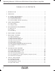
Operating Manual 6125A and 4200A Multi-Channel Power Amplifier Table Of Contents 2 1 INTRODUCTION . . . . . . . . . . . . . . . . . . . . . . . . . . . . . . . . . . . . . . . . . . . . . . . . . . . 4 2 UNPACKING . . . . . . . . . . . . . . . . . . . . . . . . . . . . . . . . . . . . . . . . . . . . . . . . . . . . . . . 4 3 AC 3.1 3.2 3.3 4 CABLE REQUIREMENTS . . . . . . . . . . . . . . . . . . . . . . . . . . . . . . . . . . . . . . . . . . . . 5 4.1 Input Cables . . . . . . . . . . . . . . . .
Operating Manual 6125A and 4200A Multi-Channel Power Amplifier 10 DESIGN THEORY . . . . . . . . . . . . . . . . . . . . . . . . . . . . . . . . . . . . . . . . . . . . . . . . . . 13 11 TROUBLESHOOTING TIPS . . . . . . . . . . . . . . . . . . . . . . . . . . . . . . . . . . . . . . . . . . 11.1 No Audio Output . . . . . . . . . . . . . . . . . . . . . . . . . . . . . . . . . . . . . . . . . . . . 11.2 Distorted Sound . . . . . . . . . . . . . . . . . . . . . . . . . . . . . . . . . . . . . . . . . . . . .
Operating Manual 6125A and 4200A Multi-Channel Power Amplifier 1. INTRODUCTION The 6125A and 4200A power amplifiers combine the efficiency of a MOSFET high-speed switching output stage with the sophistication of modern microprocessor and DSP technology to produce a multi-channel amplifier with unprecedented versatility and power in a single 3RU package.
Operating Manual 6125A and 4200A Multi-Channel Power Amplifier 4. CABLE REQUIREMENTS 5. 4.1 Input Cables Be sure to use shielded cable whether balanced or unbalanced. Shielding which is properly grounded will protect the signal from outside electrical interference such as RF, fluorescent lighting, and computer/display emissions.
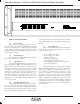
Operating Manual 6125A and 4200A Multi-Channel Power Amplifier 6. FRONT PANEL FEATURES 6.1 Power Switch When the unit is switched on there is a five second delay, during which time the PROTECT circuit will activate, disconnecting the speakers from the amplifier output. When turning off the amplifier, the load is removed instantly, and the protect LED will briefly turn on as the power supply discharges. 6.2 Signal Indicator The signal present LEDs illuminate at an input level of about 13mVrms (-35.5dBu).
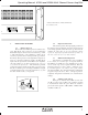
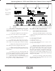
Operating Manual 6125A and 4200A Multi-Channel Power Amplifier * Model 6125A shown - Model 4200A only has channels 1-4. 7. REAR PANEL FEATURES 7.1 Input Connectors The 6125A and 4200A inputs use balanced two piece "Euroblock" style connectors. It is recommended that balanced input connections be used whenever possible to take full advantage of the amplifier's common mode rejection properties, and to reduce ground-loop problems.
Operating Manual 6125A and 4200A Multi-Channel Power Amplifier Model 6125A shown. Model 4200A has only four channels. 7.5 Input Level Controls Input Level Controls attenuate input signal from 0dB down to -∞. For best performance, Altec recommends that the level controls be operated at full level (0 dB attenuation). In STEREO mode, each level control corresponds directly to the input signal on its respective channel.
Operating Manual 6125A and 4200A Multi-Channel Power Amplifier Model 6125A shown. Model 4200A has only four channels. Outputs 7.9 AC Inlet The 6125A and 4200A amplifiers can be configured by the customer for operation at either 115VAC or 230VAC mains. Switching from one to the other simply requires the following steps: If the mains voltage is 220-250VAC, the required fuse is MDA 10, 250V, and the required power cord is 3wire grounded, 10 Amp (18AWG) minimum. 1.
Operating Manual 6125A and 4200A Multi-Channel Power Amplifier In all cases, the amplifier will restart the signal processing module after a short delay and will reconnect the speakers after several seconds if no further fault conditions exist. This allows the servo circuitry to bring any residual DC offsets to zero before speakers are connected. Specific conditions resulting in a fault are as follows: 8.1 Power supply undervoltage - less than about 55 volts on the either supply rail.
Operating Manual 6125A and 4200A Multi-Channel Power Amplifier 9.
Operating Manual 6125A and 4200A Multi-Channel Power Amplifier 9.
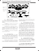
Operating Manual 6125A and 4200A Multi-Channel Power Amplifier 10. DESIGN THEORY 11. TROUBLESHOOTING TIPS The 6125A and 4200A amplifiers are based on stereo driver modules that use digital processing to generate a spread-spectrum switching pattern between about 200KHz and 1.5MHz, depending on input signal amplitude and frequency.
Operating Manual 6125A and 4200A Multi-Channel Power Amplifier 11.2 Distorted Sound 11.3 1.) Clip LED is flashing regularly Amplifier is being overdriven. Turn down the input level control, or reduce the output level from the signal source. 2.) Clip LED is not flashing at all Amplifier input signal may be exceeding input headroom, which is greater than +12dBu, or 3.4V rms (measured using continuous 1kHz sine wave). Incoming signal level higher than +12.8 dBu will cause distortion in the amplifier.
Operating Manual 6125A and 4200A Multi-Channel Power Amplifier 13. SPECIFICATIONS Typical Idle Current 6125A 120V: 0.81A 240V: 0.42A *Power Output (Maximum Average Power, 0.
Operating Manual 6125A and 4200A Multi-Channel Power Amplifier Altec Lansing Pr ofessional Professional 1000 W. Wilshire Blvd.