AL2094S Designers Guide Analog Socket Modem AL2094S Series Designer’s Guide Version 102 Released January 4, 2008 AL2094S-E00-102 xmodus swiss GmbH 1 / 30
AL2094S Designers Guide Information provided by xmodus swiss GmbH is believed to be accurate and reliable. However, no responsibility is assumed by xmodus swiss GmbH for its use, nor any infringement of patents or other rights of third parties which may result from its use. No license is granted by implication or otherwise under any patent rights of xmodus other than for circuitry embodied in xmodus. Xmodus swiss GmbH reserves the right to change circuitry at any time without notice.
AL2094S Designers Guide Table of Contents 1. INTRODUCTION ..........................................................................................................5 1.1 Overview.......................................................................................................................5 1.2 FEATURES ..................................................................................................................6 1.2.1 General Modem Features.......................................................
AL2094S Designers Guide 3.1.1 Phone Line Interface...................................................................................15 3.1.2 Call Progress Speaker Interface .................................................................15 3.1.3 Serial DTE Interface and Indicator Outputs ................................................15 3.1.4 External Reset Input ...................................................................................15 3.1.
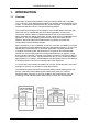
AL2094S Designers Guide 1. INTRODUCTION 1.1 Overview The xmodus AL2094S Socket Modem Family provides the OEM with a complete V.92, V.34 and V.32bis data/fax/voice modem in a compact socket-mountable DIL-40 module. This designer's guide describes the modem hardware. AT commands and S registers are defined in the AT Command Reference Manual. The compact size and high level of integration of the Socket Modem minimizes real estate and cost for motherboard and box modem applications.
AL2094S Designers Guide 1.2 FEATURES 1.2.1 General Modem Features • • • • • • • • • • • • • • • • 1.2.2 Data modem QuickConnect and Modem-on-hold functions ITU-T V.92 , V.34 , V.32bis, V.32, V.22 bis, V.22, V.23, and V.21; Bell 212A and Bell 103 V.250 and V.251 commands V.22 bis fast connect Data compression and error correction V.44 data compression V.42 bis and MNP 5 data compression V.
AL2094S Designers Guide 1.3 TECHNICAL OVERVIEW 1.3.1 General Description Modem operation, including dialing, call progress, telephone line interface, telephone handset interface, and host DTE interface functions are supported and controlled through the V.250, V.251, and V.253-compatible command set. 1.3.2 MCU Firmware MCU firmware performs processing of general modem control, command sets, data modem, error correction and data compression (ECC), fax class 1, fax class 1.
AL2094S Designers Guide 1.3.5 Synchronous Access Mode (SAM) - Video Conferencing V.80 Synchronous Access Mode between the modem and the host/DTE is provided for hostcontrolled communication protocols, e.g., H.324 video conferencing applications. Voice-callfirst (VCF) before switching to a videophone call is also supported. 1.3.6 Worldwide Operation The modem operates in TBR21-compliant and other countries.
AL2094S Designers Guide 2. TECHNICAL SPECIFICATIONS 2.1 Serial DTE Interface Operation 2.1.1 Automatic Speed/Format Sensing Command Mode and Data Modem Mode. The modem can automatically determine the speed and format of the data sent from the DTE.
AL2094S Designers Guide 2.2.3 Modem Handshaking Protocol If a tone is not detected within the time specified in the S7 register after the last digit is dialed, the modem aborts the call attempt. 2.2.4 Call Progress Tone Detection Ringback, equipment busy, congested tone, warble tone, and progress tones can be detected in accordance with the applicable standard. 2.2.5 Answer Tone Detection Answer tone can be detected over the frequency range of 2100 ± 40 Hz in ITU-T modes and 2225 ± 40 Hz in Bell modes.
AL2094S Designers Guide 2.3 Data Mode Data mode exists when a telephone line connection has been established between modems and all handshaking has been completed. 2.3.1 Speed Buffering (Normal Mode) Speed buffering allows a DTE to send data to, and receive data from, a modem at a speed different than the line speed. The modem supports speed buffering at all line speeds. 2.3.2 Flow Control DTE-to-Modem Flow Control.
AL2094S Designers Guide 2.4 Modem-on-Hold The Modem-on-Hold (MOH) function (V.92 models only) enables the modem to place a data call to the Internet on hold while using the same line to accept an incoming or place an outgoing voice call. This feature is available only with a connection to a server supporting MOH. MOH can be executed through either of two methods: • • One method is to enable MOH through the +PMH command.
AL2094S Designers Guide 2.7 Telephony Extensions The following telephony extension features are supported and can be typically be implemented in designs for set-top box applications and TAM software applications to enhance end-user experience: • • • 2.7.1 Line In Use detection Extension Pickup detection Remote Hang-up detection Line In Use Detection The Line In Use Detection feature can stop the modem from disturbing the phone line when the line is already being used.
AL2094S Designers Guide • • • • 2.10 Calling tone is generated in accordance with V.25. Calling tone may be toggled (enabled/disabled) by inclusion of a “^” character in a dial string. It may also be disabled. Frequency and cadence of tones for busy, ringback, congested, warble, dial tone 1, and dial tone 2. Answer tone detection period. Blacklist parameters.
AL2094S Designers Guide 3. HARDWARE INTERFACE 3.1 AL2094S Modem Hardware Pins and Signals 3.1.1 Phone Line Interface The phone-line interface signals are: • • 3.1.2 TIP RING Call Progress Speaker Interface The call progress speaker interface signal is: • Digital speaker output (DSPKOUT); output DSPKOUT is a square wave output in Data/Fax mode used for call progress or carrier monitoring. This output can be optionally connected to a low-cost on-board speaker, e.g.
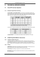
AL2094S Designers Guide FIGURE 3-1. AL2094S MODEM HARDWARE SIGNALS 1 2 3 4 5 6 7 8 9 19 20 GND GND VCC1 VCC2 RESET NC SPKOUT TDCLK RDCLK NC RING RXD TXD DTR DCD DCD CTS RTS RI NC NC TIP 40 39 38 37 36 35 34 33 32 22 21 Table 3-1.
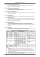
AL2094S Designers Guide Table 3-2. Signal Descriptions Label Pin I/O I/O Type VCC 3,4 P PWR Digital Supply Voltage. Connect to VCC (+3.3V, filtered). GND 1,2 G GND RESET 5 I IC/OC SPKOUT 7 O It/Ot2 Digital Ground. Connect to digital ground (GND). Reset. . Open collector input/output. Drive only with opencollector circuit. The active low RESET# input resets the Modem logic and clears the internal SRAM.
AL2094S Designers Guide Table 3-3. Signal Descriptions (Cont'd) Label Pin I/O I/O Type RTS 34 I Ithpu RXCLK 9 O Itpu/Ot2 TXCLK 8 O Itpu/Ot2 Signal Name/Description Request To Send (EIA CA/ITU-T CT105). RTS# input ON (low) indicates that the DTE is ready to send data to the modem. In the command state, the modem ignores RTS#. In asynchronous operation, the modem ignores RTS# unless RTS/CTS flow control is selected by the &Kn command.
AL2094S Designers Guide 3.3 Electrical and Environmental Specifications 3.3.1 Operating Conditions, Maximum Ratings, Power Requirements. The operating conditions are specified in Table 3-9. The absolute maximum ratings are listed in Table 3-10. The current and power requirements are listed in Table 3-11. Table 3-9. Operating Conditions Parameter Supply Voltage Operating Ambient Temperature Symbol VDD TA Limits + 3.0 to +3.6 0 to + 70 Units VDC °C Symbol VDD VIN TSTG VIN VHZ Limits -0.5 to + 4.
AL2094S Designers Guide 3.3.2 Interface and Timing Waveforms 3.3.2.1 Serial DTE Interface The serial DTE interface waveforms for 4800 and 9600 bps are illustrated in Figure 3-5. FIGURE 3-5.
AL2094S Designers Guide 3.4 DAA Interface The Socket Modem is configured to be an on-board DAA (World Class DAA). Provide TIP and RING signals from the telco jack to pins 20 and 21 of the Socket Modem. Only EMI suppression and surge protection components may be used. If other components are used, the PTT certification for these Socket Modems will no longer apply, and recertification will be required. The recommended telco interface for U.S. Socket Modems is shown in Figure 3-3.
AL2094S Designers Guide C1 1000PF X2/Y3 R1 0R F1 P2 P1 TS250-130 1 1 2 4 L1 8 5 RV1 TVB270SC 1 2 3 4 5 6 NC OT T R OR NC SOCKET MODEM RJ11 R2 0R C2 1000PF X2/Y3 Note: Meets ITU-T K.21 Surge Requirements FIGURE 3-4. RECOMMENDED TELEPHONE LINE INTERFACE FOR WORLD CLASS SOCKET MODEM. The common mode choke L1 is optional in both Figures 3.3 and 3.4 and it’s need depends on the characteristics of the target hardware.
AL2094S Designers Guide 4. DESIGN CONSIDERATIONS Good engineering practices must be adhered to when designing a printed circuit board (PCB) containing the Socket Modem module. Suppression of noise is essential to the proper operation and performance of the modem itself and for surrounding equipment.
AL2094S Designers Guide 4.1.2 Electromagnetic Interference (EMI) Considerations The following guidelines are offered to specifically help minimize EMI generation. Some of these guidelines are the same as, or similar to, the general guidelines but are mentioned again to reinforce their importance. In order to minimize the contribution of the Socket Modem-based design to EMI, the designer must understand the major sources of EMI and how to reduce them to acceptable levels. 4.2 1.
AL2094S Designers Guide 4.3 Manufacturing Considerations The Socket Modem has been designed to be mounted onto the host board in one of two ways. The first method consists of soldering a DIP-40 socket to the host board and inserting the Socket Modem into the socket. The second way is to solder the Socket Modem directly to the host board. The most efficient way to do this is through a wave solder process. The recommended hole size for the Socket Modem pins is 0.036 in. ±0.003 in. in diameter.
AL2094S Designers Guide 5. PACKAGE DIMENSIONS Package Dimensions are shown in Figure 5-1. Bottom View 53 mm 20.3 mm 1,6mm 3,5 mm ∅ 0.5mm 4,8 mm 2,54mm 3,4mm Figure 5-1.
AL2094S Designers Guide 6. SOCKET MODEM APPROVALS The Socket Modem module is approved as a host-independent modem card. To maintain type approvals, permits and/or licenses valid, the guidelines described in this document must be followed. 6.1 Considerations for Telecom Approvals The Socket Modem has been assessed and has been found to comply with the relevant harmonized standards as defined by the European ETSI Directive (ETSI TC-TE). These standards are: 6.1.
AL2094S Designers Guide 6.2.2 Power Supply [EN60950-1:2001, 1.6] Before installing the Socket Modem in a host system, the installer must ensure that the power drawn by the card, together with the host and any auxiliary cards drawing power from the host, is within the rating of the host power supply unit. The Socket Modem's power consumption is typically 0.25 W (+3.3 Vdc). 6.2.3 Clearances, Creepage Distances and Distances through Insulation [EN60950-1:2001, 2.10.3 and 2.10.
AL2094S Designers Guide Clearance and creepage between primary (mains) and secondary circuits according EN 60950-1:2001, clause 2.10.3.2 table 2H and clause 2.10.4 table 2L. Minimum distances between primary and secondary circuits (f.g. for mains voltage 230 VAC): Clearance = 4 mm Creepage = 5 mm Failure to maintain these minimum distances would invalidate the approval.
AL2094S Designers Guide 6.3 Considerations for EMC 6.3.1 EMC Compliance (European Countries) The Socket Modem has been assessed with respect to emission of and immunity to electromagnetic disturbances and has been found to comply with the relevant harmonized standards as defined by the European EMC Directive (89/336/EEC).