
Specifications


AL2094S Designers Guide
AL2094S-E00-102 xmodus swiss GmbH Seite 15 / 30
3
3
.
.
H
H
A
A
R
R
D
D
W
W
A
A
R
R
E
E
I
I
N
N
T
T
E
E
R
R
F
F
A
A
C
C
E
E
3.1 AL2094S Modem Hardware Pins and Signals
3.1.1 Phone Line Interface
The phone-line interface signals are:
• TIP
• RING
3.1.2 Call Progress Speaker Interface
The call progress speaker interface signal is:
• Digital speaker output (DSPKOUT); output
DSPKOUT is a square wave output in Data/Fax mode used for call progress or carrier
monitoring. This output can be optionally connected to a low-cost on-board speaker, e.g.,
a sounducer, or to an analog speaker circuit.
3.1.3 Serial DTE Interface and Indicator Outputs
The supported DTE interface signals are:
• Serial Transmit Data input (TXD#)
• Serial Receive Data output line (RXD#)
• Clear to Send output (CTS#)
• Received Line Signal Detector (DCD#)
• Ring Indicator (RI#)
• Data Terminal Ready control input (DTR#)
• Request to Send control input (RTS#)
Additional clock signals provided for synchronous mode are:
• Receive Data Clock (RXCLK#)
• Transmit Data Clock (TXCLK#)
3.1.4 External Reset Input
The supported reset input interface signals are:
• External Reset Input (EXTRESET#)
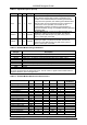
3.1.5 AL2094S Modem Pin Assignments and Signal Definitions
AL2094S Modem DIL-40 hardware interface signals are shown by major interface in Figure
3-1, are shown by pin number in Figure 3-2, and are listed by pin number in Table 1-1.
AL20XX Modem hardware interface signals are defined in Table 3-2.
I/O types are defined in Table 3-3.
DC electrical characteristics are listed in Table 3-4.