
Specifications


AL2094S Designers Guide
AL2094S-E00-102 xmodus swiss GmbH Seite 17 / 30
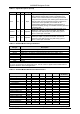
Table 3-2. Signal Descriptions
Label Pin I/O I/O Type Signal Name/Description
VCC 3,4 P PWR Digital Supply Voltage. Connect to VCC (+3.3V, filtered).
GND 1,2 G GND Digital Ground. Connect to digital ground (GND).
RESET 5 I IC/OC
Reset. . Open collector input/output. Drive only with open-
collector circuit.
The active low RESET# input resets the Modem logic and
clears the internal SRAM. RESET# low holds the modem in
the reset state; RESET# going high releases the modem from
the reset state. RESET# is connected to a built-in reset circuit
on the Socket Modem.
Connect to Ground through an 1nF capacitor to ensure good
ESD immunity and to comply with ESD tests according to EN
61000-4-2.
SPKOUT 7 O It/Ot2
Modem Speaker Digital Output. The DSPKOUT digital
output reflects the received analog input signal digitized to
TTL high or low level by an internal comparator.
TIP 21 P Passive
TIP Signal from Telco/PTT
RING 20 P Passive
RING Signal from Telco/PTT
TXD 39 I It/Ot2
Transmitted Data (EIA BA/ITU-T CT103). The DTE uses the
TXD# line to send data to the modem for transmission over
the telephone line or to transmit commands to the modem.
RXD 40 O It/Ot2
Received Data (EIA BB/ITU-T CT104). The modem uses the
RXD# line to send data received from the telephone line to the
DTE and to send modem responses to the DTE. During
command mode, RXD# data represents the modem
responses to the DTE.
CTS 35 O Ith/Ot8
Clear To Send (EIA CB/ITU-T CT106). CTS# output ON (low)
indicates that the modem is ready to accept data from the
DTE. In asynchronous operation, in error correction or normal
mode, CTS# is always ON (low) unless RTS/CTS flow control
is selected by the &Kn command. In synchronous operation,
the modem also holds CTS# ON during asynchronous
command state. The modem turns CTS# OFF immediately
upon going off-hook and holds CTS# OFF until both DSR#
and DCD# are ON and the modem is ready to transmit and
receive synchronous data. The modem can also be
commanded by the &Rn command to turn CTS# ON in
response to an RTS# OFF-to-ON transition.
DCD 37 O Ith/Ot8
Received Line Signal Detector (EIA CF/ITU-T CT109).
When AT&C0 command is not in effect, DCD# output is ON
when a carrier is detected on the telephone line or OFF when
carrier is not detected.
DSR 36 O Ith/Ot8
Data set ready. This signal is not supported. This output is
hardwired to the DCD signal. Same as pin 37.
RI 33 O Ith/Ot8
Ring Indicator (EIA CE/ITU-T CT125). RI# output ON (low)
indicates the presence of an ON segment of a ring signal on
the telephone line.
DTR 38 I It
Data Terminal Ready (EIA CD/ITU-T CT108). The DTR#
input is turned ON (low) by the DTE when the DTE is ready to
transmit or receive data. DTR# ON prepares the modem to be
connected to the telephone line, and maintains the connection
established by the DTE (manual answering) or internally
(automatic answering). DTR# OFF places the modem in the
disconnect state under control of the &Dn and &Qn
commands.