
Specifications


AL2094S Designers Guide
AL2094S-E00-102 xmodus swiss GmbH Seite 19 / 30
3.3 Electrical and Environmental Specifications
3.3.1 Operating Conditions, Maximum Ratings, Power Requirements.
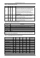
The operating conditions are specified in Table 3-9.
The absolute maximum ratings are listed in Table 3-10.
The current and power requirements are listed in Table 3-11.
Table 3-9. Operating Conditions
Parameter Symbol Limits Units
Supply Voltage VDD + 3.0 to +3.6 VDC
Operating Ambient Temperature T
A
0 to + 70 °C
Table 3-10. Absolute Maximum Ratings
Parameter Symbol Limits Units
Supply Voltage VDD -0.5 to + 4.0 VDC
Input Voltage V
IN
-0.5 to (VGG +0.5)* VDC
Storage Temperature Range T
STG
-55 to + 125 °C
Analog Inputs V
IN
-0.3 to (VAA + 0.5) VDC
Voltage Applied to Outputs in
High Impedance (Off) State
V
HZ
-0.5 to (VGG + 0.5)* VDC
DC Input Clamp Current I
IK
±20 mA
DC Output Clamp Current I
OK
±20 mA
Static Discharge Voltage (25°C) V
ESD
±2500 VDC
Latch-up Current (25°C) I
TRIG
±400 mA
* VGG = +3.3V ± 0.3V or +5V ± 5%.
Handling CMOS Devices
The device contains circuitry to protect the inputs against damage due to high static
voltages. However, it is advised that normal precautions be taken to avoid application of
any voltage higher than maximum rated voltage.
An unterminated input can acquire unpredictable voltages through coupling with stray
capacitance and internal cross talk. Both power dissipation and device noise immunity
degrades. Therefore, all inputs should be connected to an appropriate supply voltage.
Input signals should never exceed the voltage range from -0.5V to VGG + 0.5V. This
prevents forward biasing the input protection diodes and possibly entering a latch up
mode due to high current transients.
Table 3-11. Current and Power Requirements
Mode
Typical
Current
(Ityp)
(mA)
Maximum
Current
(Imax)
(mA)
Typical
Power
(Ptyp)
(mW)
Maximum
Power
(Pmax)
(mW)
Normal Mode: Off-hook, normal data connection 66 73 220 240
Normal Mode: On-hook, idle, waiting for ring 61 67 200 220
Sleep Mode 17 19 56 63
Notes:
1. Operating voltage: VDD = +3.3V ± 0.3V.
2. Test conditions: VDD = +3.3V for typical values; VDD = +3.6V for maximum values.
3. Input Ripple ≤ 0.1 Vpeak-peak.
4. f = Internal frequency.
5. Maximum current computed from Ityp: Imax = Ityp * 1.1.
6. Typical power (Ptyp) computed from Ityp: Ptyp = Ityp * 3.3V; Maximum power (Pmax) computed from Imax:
Pmax = Imax * 3.6V.