
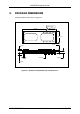
Specifications


AL2094S Designers Guide
AL2094S-E00-102 xmodus swiss GmbH Seite 21 / 30
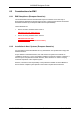
3.4 DAA Interface
The Socket Modem is configured to be an on-board DAA (World Class DAA).
Provide TIP and RING signals from the telco jack to pins 20 and 21 of the Socket Modem.
Only EMI suppression and surge protection components may be used. If other components
are used, the PTT certification for these Socket Modems will no longer apply, and
recertification will be required.
The recommended telco interface for U.S. Socket Modems is shown in Figure 3-3.
The recommended telco interface for World Class Socket Modems is shown in Figure 3-4.
TIP and RING signal traces are to be no closer than 2.5mm (0.1") from any other traces for
European applications. 2.5mm spacing must be used if the host board is to support both
U.S. and European Socket Modems.
P2
SOCKET MODEM
1
2
R2
0R
R1
0R
F1
F1250T
C2
1000PF
C1
1000PF
P1
RJ11
1
2
3
4
5
6
NC
OT
T
R
OR
NC
X2/Y3
X2/Y3
L1
1
4
8
5 RV1
P3100SC
Note: Meets FCC Part 68 Type A and Type B Surge Requirements (Type A Non-Operational)
F
IGURE 3-3. RECOMMENDED TELEPHONE LINE INTERFACE FOR U.S. SOCKET MODEM