
Specifications

© March 2009 Altera Corporation Cyclone III 3C120 Development Board Reference Manual
2. Board Components
Introduction
This chapter introduces all the important components on the Cyclone III development
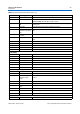
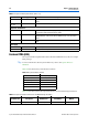
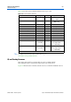
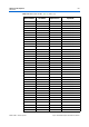
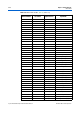
board. Figure 2–1 illustrates all component locations and Tabl e 2–1 describes
component features.
The chapter is divided into the following sections:
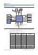
■ “Featured FPGA (U20)” on page 2–4
■ “MAX II CPLD” on page 2–6
■ “Configuration, Status, and Setup Elements” on page 2–14
■ “Clocking Circuitry” on page 2–23
■ “General User Interfaces” on page 2–26
■ “Communication Ports and Interfaces” on page 2–37
■ “On-Board Memory” on page 2–48
■ “Power Supply” on page 2–62
■ “Statement of China-RoHS Compliance” on page 2–64
1 A complete set of board schematics, a physical layout database, and GERBER files for
the Cyclone III development board are installed in the Cyclone III Development Kit
documents directory.
f For information about powering up the development board and installing the demo
software, refer to the Cyclone III Development Kit User Guide.
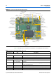
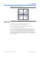
Board Overview
This section provides an overview of the Cyclone III development board, including an
annotated board image and component descriptions.
Figure 2–1 shows the top view of the Cyclone III development board.