
Specifications

2–32 Chapter 2: Board Components
General User Interfaces
Cyclone III 3C120 Development Board Reference Manual © March 2009 Altera Corporation
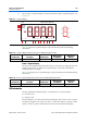
Character LCD (J4)
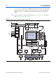
The board contains a single 14-pin 0.1” pitch dual-row header, used to interface to a
16-character by 2-line LCD display, Lumex (part number LCM-S01602DSR/C). The
LCD has a 14-pin receptacle that mounts directly to the board’s 14-pin header, so it
can be easily removed for access to components under the display—or to use the
header for debugging or other purposes.
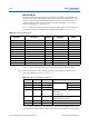
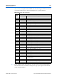
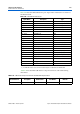
Ta bl e 2–36 summarizes the character LCD interface pins. Signal name and direction
are relative to the Cyclone III FPGA. For functional descriptions, see Tab le 2–37.
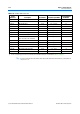
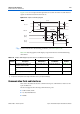
Ta bl e 2–37 shows pin definitions, and is an excerpt from the Lumex data sheet.
f For more information such as timing, character maps, interface guidelines, and
related documentation, visit www.lumex.com.
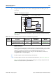
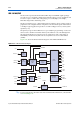
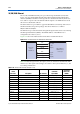
Figure 2–8 shows a functional block diagram of the Lumex LCD display device. The
8-bit data bus is shared with the graphics LCD, but the control signals are all separate.
Table 2–36. Character LCD Header I/O
Board
Reference Description
I/O
Standard
Schematic
Signal Name
Cyclone III Pin
Number
J22 pin 7 LCD data bus bit 0 2.5 V LCD_DATA0 AA4
J22 pin 8 LCD data bus bit 1 2.5 V LCD_DATA1 AD1
J22 pin 9 LCD data bus bit 2 2.5 V LCD_DATA2 V8
J22 pin 10 LCD data bus bit 3 2.5 V LCD_DATA3 AB5
J22 pin 11 LCD data bus bit 4 2.5 V LCD_DATA4 AE2
J22 pin 12 LCD data bus bit 5 2.5 V LCD_DATA5 V5
J22 pin 13 LCD data bus bit 6 2.5 V LCD_DATA6 V6
J22 pin 14 LCD data bus bit 7 2.5 V LCD_DATA7 AB3
J22 pin 4 LCD data/command select 2.5 V LCD_D_Cn D27
J22 pin 5 LCD write enable 2.5 V LCD_D_WEn AC4
J22 pin 6 LCD chip select 2.5 V LCD_D_CSn AB24
Table 2–37. Character LCD Display Pin Definitions
Pin Number Symbol Level Function
1V
DD
— Power supply 5 V
2V
SS
— GND (0 V)
3V
0
— For LCD drive
4 RS H/L Register select signal
H: Data input
L: Instruction input
5 R/W H/L H: Data read (module to MPU)
L: Data write (MPU to module)
6 E H, H to L Enable
7~14 DB0~DB7 H/L Data bus, software selectable 4 or 8 bit mode