
Specifications

Chapter 2: Board Components 2–37
Communication Ports and Interfaces
© March 2009 Altera Corporation Cyclone III 3C120 Development Board Reference Manual
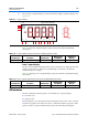
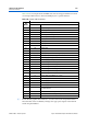
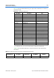
Figure 2–10 is an excerpt from the Optrex data sheet and shows the module interface
signals for both read and write transactions.
f For more information about timing parameters, visit www.optrex.com.
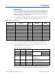
Ta bl e 2–41 lists the graphics LCD display component reference and manufacturing
information.
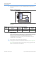
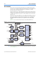
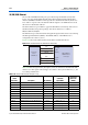
Communication Ports and Interfaces
This section describes the board’s communication ports and interfaces relative to the
Cyclone III device.
The board supports the following communication ports:
■ USB 2.0 MAC/PHY
■ 10/100/1000 Ethernet
■ HSMC
Figure 2–10. Graphics LCD Timing Diagram
A0, CS1
D0~D7
(Write)
D0~D7
(Read)
WR, RD
t
CYC8
t
CCH(W/R)
t
CCL(W/R)
t
AW8
t
AH8
t
DS8
t
ACC8
t
OH8
t
DH8
t
f
t
r
Table 2–41. Graphics LCD Display Component Reference and Manufacturing Information
Board
Reference Description Manufacturer
Manufacturing
Part Number
Manufacturer
Website
J13 FPC/FFC 30-position flick lock
connector, bottom contact
Hirose Electronics, Co. FH12S-30S-0.55H(55) www.hirose.com
128 × 64 graphics module, blue LCD
(1)
Optrex America, Inc. F-51852GNFQJ-LB-AIN www.optrex.com
128 × 64 graphics module, green LCD
(1)
Optrex America, Inc. F-51852GNFQJ-LG-ACN www.optrex.com
Note to Table 2–41:
(1) The Cyclone III development board is shipped with either a blue or green Optrex LED display.