
User guide

6–2 Chapter 6: Board Test System
Preparing the Board
Cyclone III FPGA Development Kit User Guide September 2010 Altera Corporation
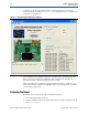
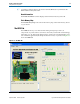
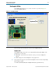
A GUI runs on the PC which communicates over the JTAG bus to a test design
running in the Cyclone III device. Figure 6–1 shows the initial GUI for a board that is
in the factory configuration.
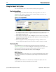
Several designs are provided to test the major board features. Each design provides
data for one or more tabs in the application. The Configure menu identifies the
appropriate design to download to the FPGA for each tab.
After successful FPGA configuration, the appropriate tab appears and allows you to
exercise the related board features. Highlights appear in the board picture around the
corresponding components.
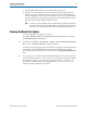
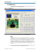
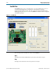
Preparing the Board
With the power to the board off, perform the following steps:
1. Connect the USB cable to the board.
2. Verify the settings for the board settings DIP switch bank (SW3) match the settings
in Table 4–2 on page 4–3.
Figure 6–1. Board Test System Graphical User Interface