EthernetBlaster Communications Cable User Guide 101 Innovation Drive San Jose, CA 95134 www.altera.com Software Version: Document Version: Document Date: 80 1.
Copyright © 2008 Altera Corporation. All rights reserved. Altera, The Programmable Solutions Company, the stylized Altera logo, specific device designations, and all other words and logos that are identified as trademarks and/or service marks are, unless noted otherwise, the trademarks and service marks of Altera Corporation in the U.S. and other countries. All other product or service names are the property of their respective holders. Altera products are protected under numerous U.S.
Contents Chapter 1. About the EthernetBlaster Communications Cable Introduction . . . . . . . . . . . . . . . . . . . . . . . . . . . . . . . . . . . . . . . . . . . . . . . . . . . . . . . . . . . . . . . . . . . . . . . . . . . . 1–1 Supported Devices . . . . . . . . . . . . . . . . . . . . . . . . . . . . . . . . . . . . . . . . . . . . . . . . . . . . . . . . . . . . . . . . . . . . 1–1 Power Requirements . . . . . . . . . . . . . . . . . . . . . . . . . . . . . . . . . . . . . . . . . . . . . . . . .
iv EthernetBlaster Communications Cable User Guide © July 2008 Altera Corporation
List of Figures v List of Figures Figure 1–1: EthernetBlaster Communications Cable Ethernet Port, Target Port, and Base Views . . . . . . 1-3 Figure 1–2: Remote Connection via Network . . . . . . . . . . . . . . . . . . . . . . . . . . . . . . . . . . . . . . . . . . . . . . . . . . 1-5 Figure 1–3: Connecting the EthernetBlaster Communications Cable to the Target Circuit Board . . . . . . 1-5 Figure 1–4: MAC Address & Host Name . . . . . . . . . . . . . . . . . . . . . . . . . . . . . . . . . . . . . . .
vi EthernetBlaster Communications Cable User Guide List of Figures © July 2008 Altera Corporation
List of Tables vii List of Tables Table 1–1: Status LED Modes . . . . . . . . . . . . . . . . . . . . . . . . . . . . . . . . . . . . . . . . . . . . . . . . . . . . . . . . . . . . . . . . 1-3 Table 1–2: Programming Modes . . . . . . . . . . . . . . . . . . . . . . . . . . . . . . . . . . . . . . . . . . . . . . . . . . . . . . . . . . . . 1-13 Table 2–1: Default Factory Settings . . . . . . . . . . . . . . . . . . . . . . . . . . . . . . . . . . . . . . . . . . . . . . . . . . . . . . . . . . .
viii EthernetBlaster Communications Cable User Guide List of Tables © July 2008 Altera Corporation
1. About the EthernetBlaster Communications Cable Introduction The EthernetBlaster communications cable connects to a standard Ethernet network port with an RJ-45 connector. This cable communicates with client systems using the TCP/IP protocol and supports both static and dynamic IP addressing.
1–2 Chapter 1: About the EthernetBlaster Communications Cable Introduction The EthernetBlaster VCC(TARGET) pin must be connected to the appropriate voltage for the device being programmed. The pull-up resistors on the target circuit board for the configuration/programming signals must be connected to the same power supply as the EthernetBlaster VCC(TARGET).
Chapter 1: About the EthernetBlaster Communications Cable Introduction 1–3 Figure 1–1.
1–4 Chapter 1: About the EthernetBlaster Communications Cable Cable Setup 1 Refer to your operating system manual or contact your network administrator to verify that your network supports DHCP services and for instruction on how to change your IP address. To maintain your computer’s IP address and change the EthernetBlaster communications cable’s default IP address, see “Configuring the EthernetBlaster Hardware to Use Static IP Addressing” on page 1–10.
Chapter 1: About the EthernetBlaster Communications Cable Cable Setup 1–5 Figure 1–2. Remote Connection via Network EthernetBlaster Communications Cable, Ethernet Port Side View ETHERNET Ethernet Jack Switch, Router, or Hub ETHERNET DC12V CAT 5 UTP Standard Cable Ethernet Jack 1 . . .
1–6 Chapter 1: About the EthernetBlaster Communications Cable Cable Setup 1 Always connect the network patch cable as instructed in step 2 before connecting the power cord. This allows the EthernetBlaster communications cable to obtain a DHCP address (if your network is configured to do so). Wait until the Status LED emits a steady green light. 5. Reconnect the power cable to the circuit board to reapply power. 6.
Chapter 1: About the EthernetBlaster Communications Cable Cable Setup 1–7 1 Refer to your operating system manual or contact your network administrator for instruction on how to change your IP address. 1 To maintain your computer’s IP address and change the EthernetBlaster communications cable default IP address, see “Configuring the EthernetBlaster Hardware to Use Static IP Addressing” on page 1–10. 9. In the EthernetBlaster login window, enter admin as the login and password as the default password.
1–8 Chapter 1: About the EthernetBlaster Communications Cable Cable Setup 2. Plug the EIA/TIA 568B connector of a crossover CAT 5 UTP 4-pair patch cable into the Ethernet jack on the EthernetBlaster communications cable, and the EIA/TIA 568A connector into your computer. See Figure 1–6 below. Figure 1–6. Direct Connection to a Computer Using a Crossover Cable Computer EthernetBlaster Communications Cable, Ethernet Port Side View ETHERNET Ethernet Jack 1 ...
Chapter 1: About the EthernetBlaster Communications Cable Cable Setup 1–9 Figure 1–7. Direct Connection to a Computer Using a Standard Cable and a Crossover Adapter Computer ETHERNET EthernetBlaster Communications Cable, Ethernet Port Side View ETHERNET Ethernet Jack DC12V EIA/TIA 568B Connector CAT 5 UTP Standard Cable ETHERNET Ethernet Jack Crossover Adapter EIA/TIA 568B Connector 3.
1–10 Chapter 1: About the EthernetBlaster Communications Cable Cable Setup Configuring the EthernetBlaster Hardware to Use Static IP Addressing By default, the EthernetBlaster communications cable is factory configured to use dynamic IP addressing. 1 Depending on your connection mode, this section assumes that you have completed the steps in “Remote Connection via Network Using Default Factory Settings” on page 1–4, or “Direct Connection to a Computer Using Default Factory Settings” on page 1–7.
Chapter 1: About the EthernetBlaster Communications Cable Cable Setup 1–11 Configuring the EthernetBlaster Hardware to Use Dynamic IP Addressing To configure the EthernetBlaster communications cable to use dynamic IP addressing, follow the directions below: 1 Depending on your connection mode, this section assumes that you have completed the steps in “Remote Connection via Network Using Default Factory Settings” on page 1–4, or “Direct Connection to a Computer Using Default Factory Settings” on page 1–7.
1–12 Chapter 1: About the EthernetBlaster Communications Cable Cable Setup Setting Up the EthernetBlaster Hardware in the Quartus II Software Use the following steps to set up the EthernetBlaster communications cable in the Quartus II software. 1. Start the Quartus II software. 2. Choose Programmer (Tools menu). 3. Click Hardware Setup. The Hardware Settings tab of the Hardware Setup dialog box is displayed. 4. Click Add Hardware. The Add Hardware dialog box is displayed.
Chapter 1: About the EthernetBlaster Communications Cable Cable Setup 1 1–13 The EthernetBlaster communications cable supports the Joint Test Action Group (JTAG), Passive Serial Programming, and Active Serial modes. Table 1–2. Programming Modes Mode Joint Test Action Group (JTAG) Mode Description Programs or configures all Altera devices supported by the Quartus II software, excluding FLEX 6000 devices. In-Socket Programming Not supported by the EthernetBlaster cable.
1–14 EthernetBlaster Communications Cable User Guide Chapter 1: About the EthernetBlaster Communications Cable Cable Setup © June 2008 Altera Corporation
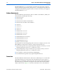
2. EthernetBlaster Communications Cable Administration Introduction This chapter describes how to administer your EthernetBlaster communications cable: ■ Managing Passwords ■ Changing the Administrative Password ■ Changing the Quartus II Remote Connection Password ■ Resetting the Hardware ■ Firmware Upgrade Managing Passwords Networking allows multiple users in both remote and local locations to use the EthernetBlaster communications cable, increasing the productivity in prototyping and debugging.
2–2 Chapter 2: EthernetBlaster Communications Cable Administration Managing Passwords 2. Click the Change Admin Password tab. See Figure 2–1 below. Figure 2–1. Change Admin Password Page 3. Enter the new administrative password in the New Password field and again in the Confirm New Password field. Click Apply. The new password takes effect immediately when logging back into the administrative web page. 1 The EthernetBlaster communications cable does not restart when the administrative password is reset.
Chapter 2: EthernetBlaster Communications Cable Administration Resetting the Hardware 2–3 Figure 2–2. Change Quartus II Remote Connection Password Page 3. Enter the new Quartus II remote connection password in the New Password field and again in the Confirm New Password field. Click Apply. The EthernetBlaster communications cable restarts. When the status LED emits a steady green light, the EthernetBlaster has successfully reset and the new password is effective.
2–4 Chapter 2: EthernetBlaster Communications Cable Administration Firmware Upgrade Table 2–1. Default Factory Settings IP Address 192.168.0.50 Subnet Mask 255.255.255.0 Default Router 192.168.0.1 DNS Server 1 0.0.0.0 DNS Server 2 0.0.0.0 Administrative Password password Quartus II Remote Connection Password password Note: (1) The host name and MAC address are located on the label on the base of your cable. The last 4 digits of the MAC address represent the “XXXX” in the host name.
Chapter 2: EthernetBlaster Communications Cable Administration Firmware Upgrade 2–5 Figure 2–4. Upgrade Firmware Page 3. Click Browse and then locate and select the firmware file on your system. Click Apply. The EthernetBlaster communications cable restarts automatically after the firmware has been successfully upgraded. When the status LED returns to a steady green state, the EthernetBlaster communications cable has restarted successfully.
2–6 EthernetBlaster Communications Cable User Guide Chapter 2: EthernetBlaster Communications Cable Administration Firmware Upgrade © June 2008 Altera Corporation
3. EthernetBlaster Communications Cable Specifications Overview This chapter provides comprehensive information about the EthernetBlaster communications cable, including the following: ■ EthernetBlaster Hardware Connections ■ Operating Conditions EthernetBlaster Hardware Connections The EthernetBlaster cable connects to an Ethernet cable with a RJ45 jack to a 10/100Base-T Ethernet hub/switch (via a straight 8-wire data cable) or a 10/100BaseT Ethernet port of a PC (via a crossover data cable).
3–2 Chapter 3: EthernetBlaster Communications Cable Specifications EthernetBlaster Hardware Connections EthernetBlaster Ethernet Jack Connection The Ethernet cable Ethernet jack connects to the EthernetBlaster communications cable Ethernet port. The Ethernet jack pin number designations are shown in Figure 3–1 below. Figure 3–1.
Chapter 3: EthernetBlaster Communications Cable Specifications Operating Conditions 3–3 Table 3–2.
3–4 Chapter 3: EthernetBlaster Communications Cable Specifications Operating Conditions Table 3–3. EthernetBlaster Cable Absolute Maximum Ratings Symbol Parameter Conditions Min Max Unit II Input current TDO or dataout –10.0 10.0 mA Io Output current TCK, TMS, TDI, nCS, nCE –10.0 10.0 mA Conditions Min Max Unit Target supply voltage, 5.0-V operation — 4.75 5.25 V Target supply voltage, 3.3-V operation — 3.0 3.6 V Target supply voltage, 2.5-V operation — 2.375 2.
Info. Additional Information Referenced Documents For more information on configuration and in-system programmability (ISP), see the following sources: ■ AN 39: IEEE 1149.
Info–2 Chapter Info: Additional Information Revision History Revision History The table below displays the revision history for the chapters in this user guide. Date and Document Version July 2008, v1.1 Changes Made Summary of Changes Updates included: December 2004, v1.0 ■ Updated the style and format. ■ Created “Additional Information” page. ■ Updated Table 1–2. ■ Updated Table 3–1. ■ Updated Software Requirements“Software Requirements” section. ■ Updated “Supported Devices” section.
Chapter Info: Additional Information Typographic Conventions Visual Cue Italic type Info–3 Meaning Internal timing parameters and variables are shown in italic type. Examples: tPIA, n + 1. Variable names are enclosed in angle brackets (< >) and shown in italic type. Example: , .pof file. Initial Capital Letters Keyboard keys and menu names are shown with initial capital letters. Examples: Delete key, the Options menu.