
Specifications

Hot-socketing circuitry prevents excess I/O leakage during power up. When the voltage ramps up very
slowly, I/O leakage is still relatively low, even after the release of the POR signal and configuration is complete.
The output buffer cannot flip from the state set by the hot-socketing circuitry at very low voltage.
To allow the CONF_DONE and nSTATUS pins to operate during configuration, the hot-socketing
Note:
feature is not applied to these configuration pins. Therefore, these pins will drive out during power
up and power down.
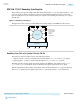
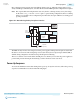
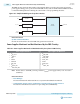
Figure 10-2: Hot-Socketing Circuitry for Cyclone V Devices
V
CCIO
PAD
R
Voltage
Tolerance
Control
Output Enable
Hot-Socket
Output
Pre-Driver
Power-On
Reset (POR)
Monitor
Weak
Pull-Up
Resistor
Input Buffer
to Logic Array
The POR circuitry monitors the voltage level of the power supplies and keeps the I/O pins tri-stated until
the device is in user mode. The weak pull-up resistor (R) in the Cyclone V input/output element (IOE) is
enabled during configuration download to keep the I/O pins from floating.
The 3.3-V tolerance control circuit allows the I/O pins to be driven by 3.3 V before the power supplies are
powered and prevents the I/O pins from driving out before the device enters user mode.
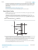
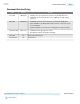
Power-Up Sequence
To ensure the minimum current draw during device power up for Cyclone V devices, follow the power-up
sequence recommendations as shown in the following figure.
Altera Corporation
Power Management in Cyclone V Devices
Send Feedback
10-3
Power-Up Sequence
CV-52010
2013.06.28