
Specifications
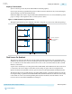
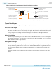
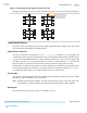
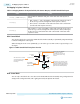
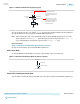
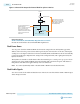
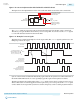

Figure 4-9: External PLL Output Clock Control Block for Cyclone V Devices
PLL Counter
Outputs
FPLL_<#>_CLKOUT pin
IOE
Internal
Logic
9
Enable/
Disable
Static Clock Select
Internal
Logic
Static Clock
Select
When the device is in user mode,
you can only set the clock select
signals through a configuration file
(.sof or .pof); they cannot be
controlled dynamically.
The clock control block feeds to a
multiplexer within the
FPLL_<#>_CLKOUT pin’s IOE. The
FPLL_<#>_CLKOUT pin is a
dual-purpose pin. Therefore, this
multiplexer selects either an internal
signal or the output of the clock
control block.
Related Information
Clock Control Block (ALTCLKCTRL) Megafunction User Guide
Provides more information about ALTCLKCTRL megafunction.
Clock Power Down
You can power down the GCLK and RCLK clock networks using both static and dynamic approaches.
When a clock network is powered down, all the logic fed by the clock network is in off-state, reducing the
overall power consumption of the device. The unused GCLK, RCLK, and PCLK networks are automatically
powered down through configuration bit settings in the configuration file (.sof or .pof) generated by the
Quartus II software.
The dynamic clock enable or disable feature allows the internal logic to control power-up or power-down
synchronously on the GCLK and RCLK networks, including dual-regional clock regions. This feature is
independent of the PLL and is applied directly on the clock network.
You cannot dynamically enable or disable GCLK or RCLK networks that drive PLLs.Note:
Clock Enable Signals
You cannot use the clock enable and disable circuit of the clock control block if the GCLK or RCLK output
drives the input of a PLL.
Clock Networks and PLLs in Cyclone V Devices
Altera Corporation
Send Feedback
CV-52004
Clock Power Down
4-12
2013.05.06