EthernetBlaster II Communications Cable User Guide EthernetBlaster II Communications Cable User Guide 101 Innovation Drive San Jose, CA 95134 www.altera.com UG-01079-1.2 P25-36448-00 Document last updated for Altera Complete Design Suite version: Document publication date: 13.
© 2014 Altera Corporation. All rights reserved. ALTERA, ARRIA, CYCLONE, HARDCOPY, MAX, MEGACORE, NIOS, QUARTUS and STRATIX are Reg. U.S. Pat. & Tm. Off. and/or trademarks of Altera Corporation in the U.S. and other countries. All other trademarks and service marks are the property of their respective holders as described at www.altera.com/common/legal.html.
Contents Chapter 1. Installing the EthernetBlaster II Communications Cable Introduction . . . . . . . . . . . . . . . . . . . . . . . . . . . . . . . . . . . . . . . . . . . . . . . . . . . . . . . . . . . . . . . . . . . . . . . . . . . . 1–1 Supported Devices . . . . . . . . . . . . . . . . . . . . . . . . . . . . . . . . . . . . . . . . . . . . . . . . . . . . . . . . . . . . . . . . . . . . 1–1 Power Requirements . . . . . . . . . . . . . . . . . . . . . . . . . . . . . . . . . . . . . . . . . . . . .
iv EthernetBlaster II Communications Cable User Guide Contents January 2014 Altera Corporation
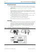
1. Installing the EthernetBlaster II Communications Cable Use the EthernetBlaster II communications cable to connect to a standard Ethernet network port with an RJ-45 connector to communicate with client systems. Using this Ethernet network, multiple users can access Altera® devices, bringing a new level of productivity to prototyping and debugging. Because design changes are downloaded directly to the device, prototyping is easy and you can accomplish multiple design iterations in quick succession.
1–2 Chapter 1: Installing the EthernetBlaster II Communications Cable Introduction Software Requirements f The EthernetBlaster II communications cable supports Windows and Linux Red Hat operating systems. You can obtain the specific operating system from the Quartus® II Readme.txt file or http://www.altera.com/support/software/os_support/oss-index.html. The EthernetBlaster II programming cable has been tested using Altera Corporation Design Suite (ACDS) tools 10.0 sp1 and later.
Chapter 1: Installing the EthernetBlaster II Communications Cable Cable Setup 1–3 The status LED on the target port side of the cable displays the operating status of the EthernetBlaster II communications cable. Table 1–1 lists each LED status mode. Table 1–1.
1–4 Chapter 1: Installing the EthernetBlaster II Communications Cable Cable Setup 1 ■ “Configuring the EthernetBlaster II Hardware to Use Static IP Addressing” on page 1–9 ■ “Configuring the EthernetBlaster II Hardware to Use Dynamic IP Addressing” on page 1–10 ■ “Setting Up the EthernetBlaster II Hardware in the Quartus II Software” on page 1–11 ■ “Removing the EthernetBlaster II Hardware from the Quartus II Software” on page 1–12 For plug and header dimensions, pin names, and operating conditio
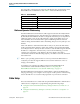
Chapter 1: Installing the EthernetBlaster II Communications Cable Cable Setup 1–5 3. Connect the 10-pin female plug of the flexible, PCB-shielded cable labeled “BLASTER SIDE” to the 10-pin female target port on the Ethernet communications cable and the 10-pin female plug of the cable labeled “TARGET SIDE” to the 10-pin male header on the target circuit board (Figure 1–3). Figure 1–3.
1–6 Chapter 1: Installing the EthernetBlaster II Communications Cable Cable Setup 7. If your network supports DHCP, you can access the EthernetBlaster II Configuration administrative web page using a web browser with the hostname as the address. The hostname is located on the label on the base of the EthernetBlaster II communications cable (Figure 1–4). Figure 1–4.
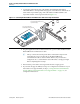
Chapter 1: Installing the EthernetBlaster II Communications Cable Cable Setup 1–7 2. In the EthernetBlaster II login window, enter admin as the login and password as the default password. The EthernetBlaster II Status page opens, displaying the status of your EthernetBlaster II communications cable, including the current IP address (Figure 1–5). Figure 1–5. EthernetBlaster II Configuration Administrative Page 1 To manage your password after the initial login, refer to “Managing Passwords” on page 2–1.
1–8 Chapter 1: Installing the EthernetBlaster II Communications Cable Cable Setup 1. Disconnect the power cable from the target circuit board. 2. Plug one end of a standard CAT 5 UTP 4-pair patch cable into the Ethernet jack on the EthernetBlaster II communications cable and the other end into your computer (Figure 1–6). Figure 1–6.
Chapter 1: Installing the EthernetBlaster II Communications Cable Cable Setup 1–9 7. In the EthernetBlaster II login window, enter admin as the login and password as the default password. The EthernetBlaster II Status page opens displaying the status of your EthernetBlaster II communications cable including the current IP address (Figure 1–5 on page 1–7). 1 To manage your password after initial login, refer to “Managing Passwords” on page 2–1. 8.
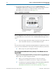
1–10 Chapter 1: Installing the EthernetBlaster II Communications Cable Cable Setup 1 Contact your network administrator if you do not know the settings to complete the Change Settings page. Figure 1–7. EthernetBlaster II Change Settings Page 3. Click Apply. The EthernetBlaster II communications cable automatically restarts. When the status LED returns to a steady green state, the EthernetBlaster II communications cable has successfully restarted and can now be added to the Quartus II software.
Chapter 1: Installing the EthernetBlaster II Communications Cable Cable Setup 1 1–11 Contact your network administrator if you do not know the settings to complete the Change Settings page. 3. Click Apply. The EthernetBlaster II communications cable automatically restarts. When the status LED returns to a steady green state, the EthernetBlaster II communications cable has successfully restarted and can now be added to the Quartus II software.
1–12 Chapter 1: Installing the EthernetBlaster II Communications Cable Cable Setup 6. Click Close to close the Hardware Setup dialog box. 7. In the Mode list, select the desired mode (Programmer window). Table 1–2 lists each mode. 1 The EthernetBlaster II communications cable supports Joint Test Action Group (JTAG), passive serial programming (PS), and active serial programming (AS). Table 1–2.
Chapter 1: Installing the EthernetBlaster II Communications Cable Cable Setup ■ January 2014 1–13 Programming & Configuring Devices ■ Setting Up Programming Hardware ■ About Programming: Chain Description Files (.
1–14 EthernetBlaster II Communications Cable User Guide Chapter 1: Installing the EthernetBlaster II Communications Cable Cable Setup January 2014 Altera Corporation
2. EthernetBlaster II Communications Cable Administration Introduction This chapter describes how to administer your EthernetBlaster II communications cable.
2–2 Chapter 2: EthernetBlaster II Communications Cable Administration Managing Passwords Changing the Administrative Password To change the administrative password, use the following steps: 1. In your browser, open and log into the EthernetBlaster II administrative web page. 1 For instructions about accessing the administrative web page using your specific connection, refer to “Cable Setup” on page 1–3. 2. Click the Change Admin Password tab (Figure 2–1). Figure 2–1. Change Admin Password Page 3.
Chapter 2: EthernetBlaster II Communications Cable Administration JTAG Clock Settings 2–3 Changing the Quartus II Remote Connection Password To change the Quartus II remote connection password, use the following steps: 1. Open and log into the EthernetBlaster II administrative web page in your browser. 1 For instructions about accessing the administrative web page using your specific connection, refer to “Cable Setup” on page 1–3. 2. Click the Change EthernetBlaster II Settings tab (Figure 2–2).
2–4 Chapter 2: EthernetBlaster II Communications Cable Administration JTAG Clock Settings w Use caution when changing the JTAG clock setting from the default setting—even if a device supports a higher frequency, your board design also affects the maximum operating frequency of your cable. Changing the JTAG Clock Frequency To change the JTAG clock frequency, use the following steps: 1. In your browser, open and log into the EthernetBlaster II administrative web page. 2.
Chapter 2: EthernetBlaster II Communications Cable Administration Resetting the Hardware 2–5 Resetting the Hardware The EthernetBlaster II communications cable reset button is located on the Ethernet port side of the hardware (Figure 2–4). Figure 2–4. Machine Reset Button ETHERNET Machine Reset DC12V Paper clip Use a small pointed object such as a paper clip to press the machine reset button to restart and reset all values to the default factory settings. Table 2–1 lists the factory default settings.
2–6 Chapter 2: EthernetBlaster II Communications Cable Administration Upgrading the Firmware Upgrading the Firmware The EthernetBlaster II communications cable has been designed to enable remote firmware upgrade when a new version of the firmware is available from Altera. New firmware may contain enhanced features, better performance, or bug fixes. c Do not turn off the EthernetBlaster II communications cable power when performing the firmware upgrade or severe damage will occur.
3.
3–2 Chapter 3: EthernetBlaster II Communications Cable Specifications EthernetBlaster II Hardware Connections EthernetBlaster II Ethernet Jack Connection The Ethernet cable Ethernet jack connects to the EthernetBlaster II communications cable Ethernet port. Figure 3–1 shows the Ethernet jack pin number designations. Figure 3–1.
Chapter 3: EthernetBlaster II Communications Cable Specifications EthernetBlaster II Hardware Connections 3–3 Table 3–2.
3–4 Chapter 3: EthernetBlaster II Communications Cable Specifications Operating Conditions Operating Conditions Table 3–3 through Table 3–5 list the maximum ratings, recommended operating conditions, and DC operating conditions for the EthernetBlaster II communication cable. Table 3–3 lists the EthernetBlaster II cable absolute maximum ratings. Table 3–3.
Chapter 3: EthernetBlaster II Communications Cable Specifications Operating Conditions Table 3–5. EthernetBlaster II Cable DC Operating Conditions Symbol VOL ICC(SYS) January 2014 3–5 (Part 2 of 2) Parameter Conditions Min Max Unit 3.3-V low-level output voltage VCC(TARGET) = 3.6 V, IOL = 1 mA — 0.4 V 2.5-V low-level output voltage VCC(TARGET) = 2.625 V, IOL = 1 mA — 0.4 V 1.8-V low-level output voltage VCC(TARGET) = 1.89 V, IOL = 1 mA — 0.4 V 1.
3–6 EthernetBlaster II Communications Cable User Guide Chapter 3: EthernetBlaster II Communications Cable Specifications Operating Conditions January 2014 Altera Corporation
Additional Information This chapter provides additional information about this user guide and Altera. Document Revision History The following table lists the revision history for this user guide. Date Version January 2014 June 2013 1.2 1.1 August 2010 1.0 Changes ■ Updated Table 3–1. ■ Removed reference to 5.0 V in “Power Requirements” on page 1–1. ■ Included reference to .tar.gz file in “Upgrading the Firmware” on page 2–6. ■ Removed references to 5.
Info–2 Additional Information Typographic Conventions Visual Cue Italic Type with Initial Capital Letters Meaning Indicate document titles. For example, Stratix IV Design Guidelines. Indicates variables. For example, n + 1. italic type Variable names are enclosed in angle brackets (< >). For example, and .pof file. Initial Capital Letters Indicate keyboard keys and menu names. For example, the Delete key and the Options menu.