
User guide


Chapter 9: Deterministic Latency PHY IP Core 9–19
Interfaces
March 2012 Altera Corporation Altera Transceiver PHY IP Core
User Guide
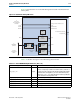
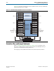
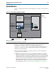
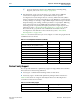
Figure 9–4 illustrates the role of the PHY Management module in the Deterministic
Latency PHY.
Table 9–17 describes the signals in the PHY Management interface.
Figure 9–4. Deterministic Latency PHY IP Core
System
Interconnect
Fabric
System
Interconnect
Fabric
Deterministic PHY PCS and PMA
Deterministic PHY IP Core
Resets
Status
Control
S
Avalon-MM
Control
S
Avalon-MM
Status
Reset
Controller
PLL
Reset
Clocks Clocks
to
Transceiver
Reconfiguration
Controller
to
Embedded
Controller
Tx Data Tx Parallel Data
Rx Data Rx Parallel Data
M
Avalon-MM
PHY
Mgmt
S
Rx Serial Data & Status
Reconfig to and from Transceiver
Tx Serial Data
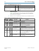
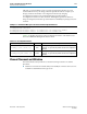
Table 9–17. Avalon-MM PHY Management Interface (Part 1 of 2)
Signal Name Direction Description
phy_mgmt_clk
Input
Avalon-MM clock input.
There is no frequency restriction for Stratix V devices; however, if
you plan to use the same clock for the PHY management interface
and transceiver reconfiguration, you must restrict the frequency
range of
phy_mgmt_clk
to 100–125 MHz to meet the specification
for the transceiver reconfiguration clock.
phy_mgmt_clk_reset
Input Global reset signal. This signal is active high and level sensitive.
phy_mgmt_address[8:0]
Input 9-bit Avalon-MM address.
phy_mgmt_writedata[31:0]
Input Input data.
phy_mgmt_readdata[31:0]
Output Output data.
phy_mgmt_write
Input Write signal.