
User guide

10–10 Chapter 10: Transceiver Reconfiguration Controller
Transceiver Calibration Functions
Altera Transceiver PHY IP Core March 2012 Altera Corporation
User Guide
Transceiver Calibration Functions
The Transceiver Reconfiguration Controller supports various calibration functions to
enhance the performance and operation of any connected transceiver PHY IP core.
This section describes the functionality of each calibration function. Refer to
Table 10–3 on page 10–5 for the resource utilization of these calibration functions.
Offset Cancellation
The offset cancellation function adjusts the offsets within the RX PMA and the CDR
parameters for process variations to achieve optimal performance. Offset cancellation
runs only once upon power-up. The RX buffers are unavailable while this function is
running. This calibration feature is run automatically and enabled by default.
Duty Cycle Calibration
The duty cycle calibration function tunes the transmitter to minimize duty cycle
distortion. Altera recommends that you enable this function for all transceiver PHY IP
cores with a data
≥ 6 Gbps. Both the TX and RX buffers are unavailable while this
function is running.
1 If you select a TX-only transceiver PHY, duty cycle calibration does not run. To run
duty cycle calibration, you can instantiate an unused receiver channel.
Auxiliary Transmit (ATX) PLL Calibration
ATX calibration tunes the parameters of the ATX PLL for optimal performance. This
function runs once after power up. You can rerun this function by writing into the
appropriate memory-mapped registers.
You should enable ATX calibration for all transceiver PHY IP cores that use an ATX
PLL. The RX buffer is unavailable while this function is running. You should run the
ATX calibration after reconfiguring the PLL. You may need to rerun ATX calibration if
you reset an ATX PLL and it does not lock after the specified lock time. When a design
includes an ATX PLL, this calibration feature runs once upon powerup. After
powerup, you must manually initiate the calibration function.
For more information on how to control the Auxiliary Transmit (ATX) PLL
Calibration refer to “ATX PLL Calibration” on page 10–17.
Refer to the “Parameter Settings” on page 10–5 section for information on how to
enabled these functions.
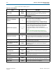
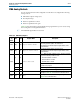
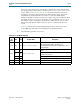
7’h38–7’h3C “Streamer Module” on page 10–22
7’h40–7’h44 “PLL Reconfiguration” on page 10–18
Table 10–8. Transceiver Reconfiguration Controller Address Map (Part 2 of 2)
Address Link