
User guide

Chapter 10: Transceiver Reconfiguration Controller 10–11
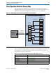
PMA Analog Controls
March 2012 Altera Corporation Altera Transceiver PHY IP Core
User Guide
PMA Analog Controls
You can use the Transceiver Reconfiguration Controller to reconfigure the following
analog controls:
■ Differential output voltage (V
OD
)
■ Pre-emphasis taps
■ Receiver equalization control
■ Receiver equalization DC gain
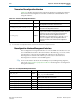
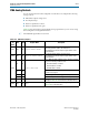
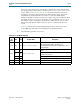
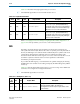
Table 10–9 lists the memory-mapped PMA analog registers that you can access using
the reconfiguration management interface.
1 All undefined register bits are reserved.
.
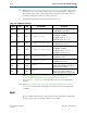
Table 10–9. PMA Analog Registers
Recon
-fig
Addr
Bits R/W Register Name Description
7’h08 [9:0] RW
logical channel number
The logical channel number. Must be specified when
performing dynamic updates. The Transceiver
Reconfiguration Controller maps the logical address to the
physical address.
7’h09 [9:0] R
physical channel address
The physical channel address. The Transceiver
Reconfiguration Controller maps the logical address to the
physical address.
7’h0A
[9] R
control and status
Error
. When asserted, indicates an error. This bit is asserted
if any of the following conditions occur:
■ The channel address is invalid.
■ The PHY address is invalid.
■ The PMA offset is invalid.
[8] R
Busy
. When asserted, indicates that a reconfiguration
operation is in progress.
[1] W
Read
. Writing a 1 to this bit triggers a read operation.
[0] W
Write
. Writing a 1 to this bit triggers a write operation.
7’h0B [5:0] RW
pma offset
Specifies the offset of the PMA analog setting to be
reconfigured. Table 10–10 describes the valid offset values.
7’h0C [6:0] RW
data
Reconfiguration data for the PMA analog settings. Refer to
Table 10–10 for valid data values.