
User guide

10–16 Chapter 10: Transceiver Reconfiguration Controller
AEQ
Altera Transceiver PHY IP Core March 2012 Altera Corporation
User Guide
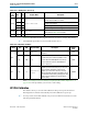
AEQ
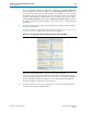
Adaptive equalization compensates for backplane losses and dispersion which
degrade signal quality. You can choose to run the AEQ once at power up or to run it
continuously to dynamically adapt to changing conditions. You can also use the AEQ
to help control the four-stage continuous time linear equalizer (CTLE) which is a
manual tool that compensates for backplane losses and dispersion.
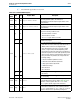
Table 10–15 lists the direct AEQ registers that you can access using Avalon-MM reads
and writes on reconfiguration management interface.
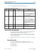
1 All undefined register bits are reserved.
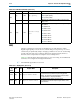
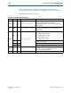
0x5
[3] RW
tap 5 polarity
Specifies the polarity of the fifth post tap as follows:
■ 0: negative polarity
■ 1: positive polarity
[2:0] RW
tap 5
Specifies the coefficient for the fifth post tap. The valid
range is 0–7.
0x6 [2:0] RW
reference voltage
level
Specifies the reference voltage: The following encodings
are defined:
■ 3’b000: 0 mV
■ 3’b001: 35 mV
■ 3’b010: 55 mV
■ 3’b011: 70 mV
■ 3’b100: 110 mV
■ 3’b101: 150 mV
■ 3’b110: 200 mV
■ 3’b111: 1000 mV
Table 10–14. DFE Offset and Values (Part 2 of 2)
Offset Bits R/W Register Name Description
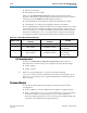
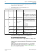
Table 10–15. AEQ Registers (Part 1 of 2)
Recon
-fig
Addr
Bits R/W Register Name Description
7’h28 [9:0] RW
logical channel number
The logical channel number of the AEQ hardware to be
accessed. Must be specified when performing dynamic
updates. The Transceiver Reconfiguration Controller maps
the logical address to the physical address.
7’h29 [9:0] R
physical channel address
The physical channel address. The Transceiver
Reconfiguration Controller maps the logical address to the
physical address.