
User guide

Chapter 10: Transceiver Reconfiguration Controller 10–25
Streamer Module
March 2012 Altera Corporation Altera Transceiver PHY IP Core
User Guide
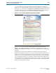
Mode 1 Avalon-MM Direct Writes for Reconfiguration
You specify this mode by writing a value of 2'b01 into bits 2 and 3 of the
control and
status
register, as indicated in Table 10–22 on page 10–23. In this mode, you can write
directly to transceiver PHY IP core registers to perform reconfiguration. Refer to
“Direct Write Reconfiguration” on page 10–29 for an example of an update using
mode 1. In mode 1, you can selectively reconfigure portions of the transceiver PHY IP
core. Unlike mode 0, mode 1 allows you to write only the data required for a
reconfiguration.
Stratix V MIF
The Stratix V MIF stores the reconfiguration data for the transceiver PHY IP cores. The
Quartus II software automatically generates MIFs after each successful compilation.
MIFs are stored in the reconfig_mif folder of the project's working directly. This
folder stores all MIFs associated with the compiled project for each transceiver PHY
IP core instance in the design. The parameter settings of PHY IP core instance reflect
the currently specified MIF. You can store the MIF in an on-chip ROM or any other
type of memory. This memory must connect to the MIF reconfiguration management
interface.
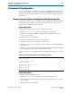
Example 10–1 shows file names for the .mif files for a design with two channels. This
design example includes two transceiver PHY IP core instances running at different
data rates. Both transceiver PHY IP core instances have two TX PLLs specified to
support both 1 Gbps and 2.5 Gbps data rates. The Quartus II software generates two
TX PLL .mif files for each PLL. The difference between the .mif files is the PLL
reference clock specified. To dynamically reconfigure the channel from the initially
specified data rate to a new data rate, you can use the MIF streaming function to load
the other .mif.
1 When reconfiguration is limited to a few settings, you can create a partial .mif that
only includes the settings that must be updated.
MIF Format
The Stratix-V MIF file is organized into records where each record contains the
information necessary to carry out the reconfiguration process. There are two types of
records: non-data records and data records. A MIF can contain a variable number of
records, depending on the target transceiver channel. Both data records and non-data
records are 16-bits long.
For both record types the high-order 5 bits represent the
length
field. A
length
field
of 5’b0, indicates a non-data record which contains an opcode. A length field that is
not zero indicates a data record.
Example 10–1. Quartus II Generated MIF Files
<project_dir>/reconfig_mif/inst0_1g_channel.mif
<project_dir>/reconfig_mif/inst0_1g_txpll0.mif
<project_dir>/reconfig_mif/inst0_1g_txpll1.mif
<project_dir>/reconfig_mif/inst0_2p5g_channel.mif
<project_dir>/reconfig_mif/inst0_2p5g_txpll0.mif
<project_dir>/reconfig_mif/inst0_2p5g_txpll1.mif