
User guide

Chapter 10: Transceiver Reconfiguration Controller 10–33
Understanding Logical Channel Numbering
March 2012 Altera Corporation Altera Transceiver PHY IP Core
User Guide
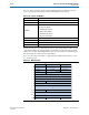
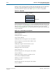
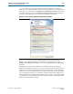
Figure 10–9 illustrates the GUI for the Transceiver Reconfiguration Controller. To
connect the Low Latency PHY IP core instance to the the Transceiver Reconfiguration
Controller, you would enter
64
for Number of reconfiguration interfaces. You would
not need to enter any values for the Optional interface grouping parameter because
all of the interfaces belong to the same transceiver PHY IP core instance.
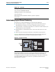
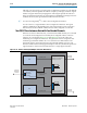
Figure 10–10 on page 10–34 shows a design with two transceiver PHY IP core
instances, each with four channels. For this design you would enter
16
for the
Number of reconfiguration interfaces and 8, 8 for the Optional interface grouping
parameter.
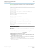
Depending upon the transceiver PHY IP core and the parameters specified, the
number of reconfiguration interfaces varies. For a single-channel, RX-only transceiver
instance, there is a single reconfiguration interface. For example, one reconfiguration
interface is created for a single-channel Low Latency PHY setup as a RX only channel.
Two reconfiguration interfaces are created for a single-channel Custom PHY setup as
a duplex channel. The reconfiguration interfaces do not appear as separate buses, but
as a single bus of concatenated reconfiguration interfaces, that grows linearly with the
number of reconfiguration interfaces.
Figure 10–9. Transceiver Reconfiguration Controller Interface Bundles