
User guide

Chapter 10: Transceiver Reconfiguration Controller 10–39
Loopback Modes
March 2012 Altera Corporation Altera Transceiver PHY IP Core
User Guide
Loopback Modes
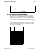
You can enable the pre- and post-CDR reverse serial loopback modes by writing the
appropriate bits of the Transceiver Reconfiguration Controller
pma_offset
register
described in Table 10–9 on page 10–11. In pre-CDR mode, data received through the
RX input buffer is looped back to the TX output buffer. In post-CDR mode, received
data passes through the RX CDR and then looped back to the TX output buffer. The
RX data is also available to the FPGA logic. In the TX channel, only the TX buffer is
active. Figure 10–14 illustrates these modes.
In addition to the pre-CDR and post-CDR loopback modes available in the
Transceiver Reconfiguration Controller register map, all the of PHYs, with the
exception of PCI Express, support serial loopback mode in both Stratix IV and
Stratix V devices. This mode is enabled by writing the
phy
_
serial
_
loopback
register
(0x061) using the Avalon-MM PHY management interface. PCI Express supports
reverse parallel loopback mode as required by the PCI Express Base Specification.
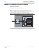
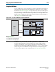
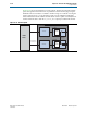
Figure 10–14. Pre- and Post-CDR Reverse Serial Loopback Paths
(1)
Notes to Figure 10–14:
(1) Grayed-out blocks are not active in these modes.
(2) Post-CDR reverse serial loopback path.
(3) Pre-CDR reverse serial loopback path.
Tx PCS
Rx PCS
Tx PMA
Serializer
Rx PMA
Deserializer
To FPGA fabric
for verication
Transceiver
CDR
(2) (3)
FPGA
Fabric