
User guide


Chapter 3: 10GBASE-R PHY IP Core 3–13
Interfaces
March 2012 Altera Corporation Altera Transceiver PHY IP Core
User Guide
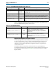
SDR XGMII RX Interface
Table 3–11 describes the signals in the SDR XGMII RX interface. This is an Avalon-ST
source interface. These signals are driven from the PCS to the MAC.
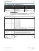
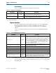
xgmii_tx_dc[53] xgmii_sdr_ctrl[5]
Lane 5 control
xgmii_tx_dc[61:54] xgmii_sdr_data[55:48]
Lane 6 data
xgmii_tx_dc[62] xgmii_sdr_ctrl[6]
Lane 6 control
xgmii_tx_dc[70:63] xgmii_sdr_data[63:56]
Lane 7 data
xgmii_tx_dc[71] xgmii_sdr_ctrl[7]
Lane 7 control
Table 3–10. Mapping from XGMII TX Bus to XGMII SDR Bus (Part 2 of 2)
Signal Name XGMII Signal Name Description
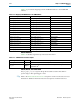
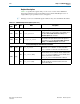
Table 3–11. SDR XGMII RX Inputs
(1)
Signal Name Direction Description
xgmii_rx_dc<n>[71:0]
Source
Contains 8 lanes of data and control for XGMII. Each lane consists of 8 bits of
data and 1 bit of control.
■ Lane 0–[7:0]/[8]
■ Lane 1–[16:9]/[17]
■ Lane 2–[25:18]/[26]
■ Lane 3–[34:27]/[35]
■ lane 4–[43:36]/[44]
■ Lane 5–[52:45]/[53]
■ Lane 6–[61:54]/[62]
■ Lane 7–[70:63]/[71]
Refer to Table 3–12 for the mapping of the
xgmii_rx_dc
data and control to the
xgmii_sdr_data
and
xgmii_sdr_ctrl
signals.
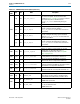
rx_ready
Output Asserted when the RX reset is complete.
rx_data_ready
[<n>-1:0]
Output
When asserted, indicates that the PCS is sending data to the MAC. Because the
readyLatency
on this Avalon-ST interface is 0, the MAC must be ready to
receive data whenever this signal is asserted. After
rx_ready
is asserted
indicating the exit from the reset state, the MAC should store store
xgmii_rx_dc
<n>
[71:0]
in each cycle where
rx_data_ready<n>
is asserted.
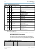
xgmii_rx_clk
Output
This clock is generated by the same reference clock that is used to generate the
transceiver clock. Its frequency is 156.25 MHz. Use this clock for the MAC
interface to minimize the size of the FIFO between the MAC and SDR XGMII RX
interface.
Note to Table 3–11:
(1) <n> is the channel number