
User guide
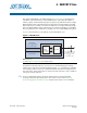

Chapter 4: XAUI PHY IP Core 4–7
Parameter Settings
March 2012 Altera Corporation Altera Transceiver PHY IP Core
User Guide
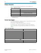
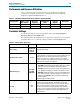
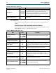
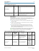
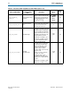
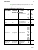
Table 4–7 lists the analog parameters with global or computed default values. You may
want to optimize some of these settings. In Table 4–7, the default value is shown in
bold type. For computed analog parameters, the default value listed is for the initial
setting, not the recomputed setting.
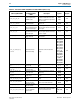
Table 4–7. Transceiver and PLL Assignments for Stratix V Devices (Sheet 1 of 3)
QSF Assignment Name
Pin Planner and
Assignment Editor
Name
Description Options Assign To
Analog Parameters with Global Default Value
CDR_BANDWIDTH_PRESET
CDR Bandwidth Preset
Specifies the CDR bandwidth preset
setting.
Auto
Low
Medium
High
PLL
instance
PLL_BANDWIDTH_PRESET
PLL Bandwidth Preset
Specifies the PLL bandwidth preset
setting
Auto
Low
Medium
High
PLL
instance
XCVR_RX_DC_GAIN
Receiver Buffer DC Gain
Control
Controls the amount of a stage
receive-buffer DC gain.
0–4 Pin
XCVR_RX_LINEAR_EQUALIZER_
CONTROL
Receiver Linear Equalizer
Control
Static control for the continuous time
equalizer in the receiver buffer. The
equalizer has 16 distinct settings from
0 –15 corresponding to the increasing
AC gain.
1 –16 Pin
Analog Parameter with Computed Default Value
XCVR_RX_COMMON_MODE_
VOLTAGE
Receiver Buffer Common
Mode Voltage
Receiver buffer common-mode
voltage.
VTT_0P80V
VTT_0P75V
VTT_0P70V
VTT_0P65V
VTT_0P60V
VTT_0P55V
VTT_0P50V
VTT_0P35V
VTT_PUP
_WEAK
VTT_PDN
WEAK
TRISTATE1
VTT_PDN_
STRONG
VTT_PUP_
STRONG
TRISTATE2
TRISTATE3
TRISTATE4
Pin
XCVR_RX_ENABLE_LINEAR_
EQUALIZER_PCIEMODE
Receiver Linear Equalizer
Control (PCI Express)
If enabled equalizer gain control is
driven by the PCS block for PCI
Express. If disabled equalizer gain
control is determined by the
XCVR_RX_LINEAR_EQUALIZER_SETT
ING
assignment.
TRUE
FALSE
Pin