
User guide

4–24 Chapter 4: XAUI PHY IP Core
Simulation Files and Example Testbench
Altera Transceiver PHY IP Core March 2012 Altera Corporation
User Guide
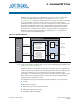
Dynamic Reconfiguration for Stratix V Devices
For Stratix V devices, each channel and each TX PLL have separate dynamic
reconfiguration interfaces. The parameter editor provides informational messages on
the connectivity of these interfaces. Example 4–1 shows the messages for a single
transceiver quad.
Although you must initially create a separate reconfiguration interface for each
channel and TX PLL in your design, when the Quartus II software compile your
design, it reduces the number of reconfiguration interfaces by merging
reconfiguration interfaces. The synthesized design typically includes a
reconfiguration interface for three channels. Allowing the Quartus II software to
merge reconfiguration interfaces gives the Fitter more flexibility in placing transceiver
channels.
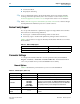
Simulation Files and Example Testbench
Refer to “Running a Simulation Testbench” on page 1–4 for a description of the
directories and files that the Quartus II software creates automatically when you
generate your XAUI PHY IP core.
f Refer to the Altera wiki for an example testbench that you can use as a starting point
in creating your own verification environment.
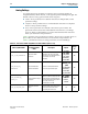
Example 4–1. Informational Messages for the Transceiver Reconfiguration Interface
PHY IP will require 8 reconfiguration interfaces for connection to the external
reconfiguration controller.
Reconfiguration interface offsets 0-3 are connected to the transceiver channels.
Reconfiguration interface offsets 4-7 are connected to the transmit PLLs.