
User guide

6–10 Chapter 6: Functional Description—High-Performance Controller
Block Description
External Memory Interface Handbook Volume 3 December 2010 Altera Corporation
Section II. DDR3 SDRAM Controller with ALTMEMPHY IP User Guide
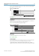
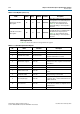
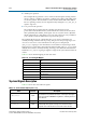
Table 6–3 shows the relationship between burst lengths and rate.
Local Burst Length 2
For a local burst length of 2, the write latency increases by two clock cycles; the read
latency increases by one clock cycle (including checking and correction).
A partial write results in a read followed by write in the ECC logic, so latency
depends on the time the controller takes to fetch the data from the particular address.
For a single-bit error, the automatic correction of memory takes place without stalling
the read cycle (if enabled), which stalls further commands to the ECC logic, while the
correction takes place.
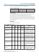
ECC Registers
Table 6–4 shows the ECC registers.
Table 6–3. Burst Lengths and Rates
Local Burst Length Rate Memory Burst Length
1Half4
2Full4
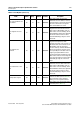
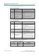
Table 6–4. ECC Registers (Part 1 of 3)
Name Address
Size
(Bits)
Attribute Default Description
Control word specifications 00 32 R/W 0000000F
This register contains all commands for
the ECC functioning.
Maximum single-bit error
counter threshold
01 32 R/W 00000001
The single-bit error counter increments
(when a single-bit error occurs) until the
maximum threshold, as defined by this
register. When this threshold is crossed,
the ECC logic generates an interrupt.
Maximum double-bit error
counter threshold
02 32 R/W 00000001
The double-bit error counter increments
(when a double-bit error occurs) until the
maximum threshold, as defined by this
register. When this threshold is crossed,
the ECC logic generates an interrupt.
Current single-bit error
count
03 32 RO 00000000
The single-bit error counter increments
(when a single-bit error occurs) until the
maximum threshold. You can find the
value of the count by reading this status
register.
Current double-bit error
count
04 32 RO 00000000
The double-bit error counter increments
(when a double-bit error occurs) until the
maximum threshold. You can find the
value of the count by reading this status
register.
Last or first single-bit error
error address
05 32 RO 00000000
This status register stores the last
single-bit error error address. It can be
cleared using the control word clear. If bit
10 of the control word is set high, the
first occurred address is stored.