
User guide

7–8 Chapter 7: Functional Description—High-Performance Controller II
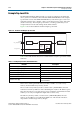
Block Description
External Memory Interface Handbook Volume 3 December 2010 Altera Corporation
Section II. DDR3 SDRAM Controller with ALTMEMPHY IP User Guide
■ A latency increase of one clock for both writes and reads.
■ Detects and corrects all single-bit errors.
■ Detects all double-bit errors.
■ Counts the number of single-bit and double-bit errors.
■ Accepts partial writes, which trigger a read-modify-write cycle, for memory
devices with DM pins.
■ Is able to inject single-bit and double-bit errors to trigger ECC correction for
testing and debugging purposes.
■ Generates an interrupt signal when an error occurs.
When a single-bit or double-bit error occurs, the ECC logic triggers the
ecc_interrupt
signal to inform you that an ECC error has occurred. When a single-bit error occurs,
the ECC logic issues an internal read to the error address, and performs an internal
write to write back the corrected data. When a double-bit error occurs, the ECC logic
does not do any error correction but it asserts the
local_rdata_error
signal to
indicate that the data is incorrect. The
local_rdata_error
signal follows the same
timing as the
local_rdata_valid
signal.
Enabling auto-correction allows the ECC logic to hold off all controller pending
activities until the correction is completed. You can choose to disable auto-correction
and schedule the correction manually when the controller is idle to ensure better
system efficiency. To manually correct ECC errors, do the following:
1. When an interrupt occurs, read the
SBE_ERROR
register. When a single-bit error
occurs, the
SBE_ERROR
register is equal to one.
2. Read out the
ERR_ADDR
register.
3. Correct the single-bit error by doing one of the following:
■ Issue a dummy write to the memory address stored in the
ERR_ADDR
register. A
dummy write is a write request with the
local_be
signal zero, that triggers a
partial write which is effectively a read-modify-write event. The partial write
corrects the data at that address and writes it back.
or
■ Enable the
ENABLE_AUTO_CORR
register using the CSR interface and issue a read
request to the memory address stored in the
ERR_ADDR
register. The read
request triggers auto-error correction to the memory address stored in the
ERR_ADDR
register.
Partial Writes
The ECC logic supports partial writes. Along with the address, data, and burst
signals, the Avalon-MM interface also supports a signal vector,
local_be
, that is
responsible for byte-enable. Every bit of this signal vector represents a byte on the
data-bus. Thus, a logic low on any of these bits instructs the controller not to write to
that particular byte, resulting in a partial write. The ECC code is calculated on all
bytes of the data-bus. If any bytes are changed, the ECC code must be recalculated
and the new code must be written back to the memory.
For partial writes, the ECC logic performs the following steps: