
User guide

Chapter 9: Timing Diagrams 9–9
DDR3 High-Performance Controllers
December 2010 Altera Corporation External Memory Interface Handbook Volume 3
Section II. DDR3 SDRAM Controller with ALTMEMPHY IP User Guide
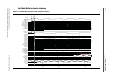
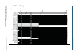
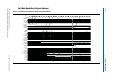
The following sequence corresponds with the numbered items in Figure 9–5:
1. The user logic requests write by asserting the
local_write_req
signal.
2. The
local_ready
signal is asserted, indicating that the controller has accepted the
request.
3. The data written to the memory for the write command.
4. The controller requests the user logic for the write data and byte-enables for the
write by asserting the
local_wdata_req
signal.
5. The write (WR) command on the command bus.
6. The valid write data on the
ctl_wdata
signal.
7. The valid data on the
mem_dq
signal goes to the controller.