
User guide

Chapter 9: Timing Diagrams 9–19
DDR3 High-Performance Controllers II
December 2010 Altera Corporation External Memory Interface Handbook Volume 3
Section II. DDR3 SDRAM Controller with ALTMEMPHY IP User Guide
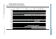
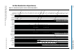
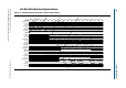
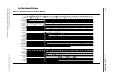
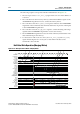
The following sequence corresponds with the numbered items in Figure 9–10:
1. The user logic requests the first read by asserting the
local_read_req
signal, and
the size and address for this read. In this example, the request is a burst of length
of 2 to the local address
0×000001
. This local address is mapped to the following
memory address in half-rate mode:
mem_row_address = 0×0000
mem_col_address = 0×0001<<2 = 0×0004
mem_bank_address = 0×00
2. The controller issues the first read memory command and address signals to the
ALTMEMPHY megafunction for it to send to the memory device.
3. The controller asserts the
afi_doing_rd
signal to indicate to the ALTMEMPHY
megafunction the number of clock cycles of read data it must expect for the first
read. The ALTMEMPHY megafunction uses the
afi_doing_rd
signal to enable its
capture registers for the expected duration of memory burst.
4. The ALTMEMPHY megafunction issues the first read command to the memory
and captures the read data from the memory.
5. The ALTMEMPHY megafunction returns the first data read to the controller after
resynchronizing the data to the
phy_clk
domain, by asserting the
afi_rdata_valid
signal when there is valid read data on the
afi_rdata
bus.
6. The controller returns the first read data to the user by asserting the
local_rdata_valid
signal when there is valid read data on the
local_rdata
bus. If
the ECC logic is disabled, there is no delay between the
afi_rdata
and the
local_rdata
buses. If there is ECC logic in the controller, there is one or three clock
cycles of delay between the
afi_rdata
and
local_rdata
buses.