
User guide

5–38 Chapter 5: Functional Description—ALTMEMPHY
Using a Custom Controller
External Memory Interface Handbook Volume 3 December 2010 Altera Corporation
Section II. DDR3 SDRAM Controller with ALTMEMPHY IP User Guide
Using a Custom Controller
The ALTMEMPHY megafunction can be integrated with your own controller. This
section describes the interface requirement and the handshake mechanism for
efficient read and write transactions.
Preliminary Steps
Perform the following steps to generate the ALTMEMPHY megafunction:
1. If you are creating a custom DDR3 SDRAM controller, generate the Altera
high-performance controller targeting your chosen Altera and memory devices.
2. Compile and verify the timing. This step is optional; refer to “Compiling and
Simulating” on page 4–1.
3. If targeting a DDR3 SDRAM device, simulate the high-performance controller
design so you can determine how to drive the PHY signals using your own
controller.
4. Integrate the top-level ALTMEMPHY design with your controller. If you started
with the high-performance controller, the PHY variation name is
<controller_name>_phy.v/.vhd. Details about integrating your controller with
Altera’s ALTMEMPHY megafunction are described in the following sections.
5. Compile and simulate the whole interface to ensure that you are driving the PHY
properly and that your commands are recognized by the memory device.
Design Considerations
This section discuss the important considerations for implementing your own
controller with the ALTMEMPHY megafunction. This section describes the design
considerations for AFI variants.
1 Simulating the high-performance controller is useful if you do not know how to drive
the PHY signals.
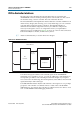
Clocks and Resets
The ALTMEMPHY megafunction automatically generates a PLL instance, but you
must still provide the reference clock input (
pll_ref_clk
) with a clock of the
frequency that you specified in the MegaWizard Plug-In Manager. An active-low
global reset input is also provided, which you can deassert asynchronously. The clock
and reset management logic synchronizes this reset to the appropriate clock domains
inside the ALTMEMPHY megafunction.
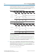
A clock output, half the memory clock frequency for a half-rate controller, is provided
and all inputs and outputs of the ALTMEMPHY megafunction are synchronous to
this clock. For AFIs, this signal is called
ctl_clk
.
There is also an active-low synchronous reset output signal provided,
ctl_reset_n
.
This signal is synchronously de-asserted with respect to the
ctl_clk
or
phy_clk
clock
domain and it can reset any additional user logic on that clock domain.