
User manual


Pin
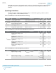
Active Serial (AS) Mode Passive Serial (PS) Mode JTAG Mode
Signal Name Description Signal Name Description Signal Name Description
6 nCE Cyclone chip
enable
- Cyclone
chip enable
PROC_RST
(1)
Cyclone chip
enable
7 DATAOUT Active serial
data out
nSTATUS Active serial
data out
- Active serial data
out
8 nCS Serial
configuration
device chip
select
- Serial
configuratio
n device
chip select
- Serial configura‐
tion device chip
select
9 ASDI Active serial
data in
DATA0 Active serial
data in
TDI Active serial data
in
10 GND Signal ground GND Signal
ground
GND Signal ground
Note: In JTAG mode, the PROC_RST pin can be used to trigger warm reset of the HPS block when
prompted via the ARM DS-5 debugger. PROC_RST is an active low signal and not an open collector
pin. As such, it is not recommended to connect PROC_RST to HPS_nRST directly. You should instead
connect this pin to a secondary device such as the MAX V CPLD, and use the device to manage the
reset network for HPS.
Circuit Board Header Connection
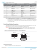
The 10-pin male header, which connects to the download cable's 10-pin female plug, has two rows of five
pins. The pins are connected to the device’s programming or configuration pins.
Caution:
If the header connection on the circuit board is a male receptacle, it must have a key notch.
Without a key notch, the 10-pin female plug will not connect. The following figure shows a
typical 10-pin male header with a key notch.
Figure 2-4: 10-Pin Male Header Dimensions - Inches and Millimeters
0.025 (0.635) Sq.
0.235 (5.969)
0.100
Side View
0.100 (2.540)
Top View
A key notch is required.
(1)
Use pin 6 for a hard processor reset under JTAG mode.
2-4
Circuit Board Header Connection
UG-01150
2015.12.11
Altera Corporation
USB-Blaster II Download Cable Specifications
Send Feedback