
User manual


JTAG Timing Constraints and Waveforms
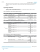
Figure 2-5: Timing Waveform for JTAG Signals (From Target Device Perspective)
TCK
TDO
TCK
TMS
TDI
tJCP
JTAG OutputJTAG Inputs
tJCH tJCL
tJPCO
tJPSU_TMS
tJPSU_TDI
tJPH
To use the USB-Blaster II at the maximum capability (24 MHz), meet the timing constraints like in the
tabe below for the target device.
The timing constraints require that you consider device specifications as well as trace propagation delays.
If you do not follow the recommended constraints, you might encounter timing issues at 24 MHz. If the
target design cannot meet these constraints, reduce the possibility of timing issues by slowing the TCK
frequency. See “Changing the TCK Frequency” section for instructions on running the USB-Blaster II at a
slower speed.
Table 2-6: JTAG Timing Constraints for the Target Device
Symbol Parameter Min Max Unit
tJCP TCK clock period 41.67 — ns
tJCH TCK clock high
time
20.83 — ns
tJCL TCK clock low time 20.83 — ns
tJPCO JTAG port clock to
JTAG Header
output
— 5.46 (2.5 V)
2.66 (1.5 V)
ns
UG-01150
2015.12.11
JTAG Timing Constraints and Waveforms
2-7
USB-Blaster II Download Cable Specifications
Altera Corporation
Send Feedback