Stratix GX Transceiver User Guide 101 Innovation Drive San Jose, CA 95134 (408) 544-7000 http://www.altera.com UG-STXGX-3.
Copyright © 2005 Altera Corporation. All rights reserved. Altera, The Programmable Solutions Company, the stylized Altera logo, specific device designations, and all other words and logos that are identified as trademarks and/or service marks are, unless noted otherwise, the trademarks and service marks of Altera Corporation in the U.S. and other countries. All other product or service names are the property of their respective holders. Altera products are protected under numerous U.S.
Contents About This User Guide ............................................................................ vii How to Contact Altera ........................................................................................................................... vii Typographic Conventions .................................................................................................................... viii Chapter 1. Introduction Gigabit Transceiver Block Highlights .........................................
Contents Stratix GX Transceiver User Guide Byte Serializer ................................................................................................................................. 8B/10B Encoder .............................................................................................................................. Basic Mode Clocking ........................................................................................................................... Basic Mode Channel Clocking .......
Contents Contents Chapter 6. GigE Mode Introduction ............................................................................................................................................ 6–1 Word Aligner .................................................................................................................................... 6–4 Rate Matcher .....................................................................................................................................
Contents Stratix GX Transceiver User Guide Chapter 9. Reset Control & Power Down Introduction ............................................................................................................................................ 9–1 Power On Reset (POR) .......................................................................................................................... 9–1 USER Reset & Enable Signals ...............................................................................................
About This User Guide How to Contact Altera Information Type Technical support Product literature For the most up-to-date information about Altera® products, go to the Altera world-wide web site at www.altera.com. For technical support on this product, go to www.altera.com/mysupport. For additional information about Altera products, consult the sources shown below. USA & Canada All Other Locations www.altera.com/mysupport/ www.altera.com/mysupport/ (800) 800-EPLD (3753) (7:00 a.m. to 5:00 p.m.
Typographic Conventions Typographic Conventions Visual Cue Stratix GX Transceiver User Guide This document uses the typographic conventions shown below. Meaning Bold Type with Initial Capital Letters Command names, dialog box titles, checkbox options, and dialog box options are shown in bold, initial capital letters. Example: Save As dialog box.
1. Introduction Introduction Stratix® GX devices combine highly advanced 3.1875-gigabit-per-second (Gbps) four-channel gigabit transceiver blocks with one of the industry’s most advanced FPGA architectures. Stratix GX devices are manufactured on a 1.5-V, 0.13-µm, all-layer copper CMOS process technology with 1.5V PCML I/O standard support. Historically, designers have used high-speed transceivers in strictly structured, line-side applications.
Transceiver Block Architecture Transceiver Block Architecture Figure 1–1 shows a block diagram of the gigabit transceiver block (GXB). You can bypass various modules if desired. Refer to“Modes of Operation” on page 1–5 for a description of the supported features in each mode. You can divide the transceiver block into an analog section and a digital section, as shown in Figure 1–1. Figure 1–1.
Introduction Transmitter & Receiver PLLs Each gigabit transceiver block contains one dedicated transmitter PLL and four dedicated receiver PLLs. These PLLs provide clocking flexibility and support a range of incoming data streams. For data transmission and recovery, these PLLs generate the required clock frequencies based upon the synthesis of an input reference clock. Each transmitter PLL supports multiplication factors of 2, 4, 5, 8, 10, 16, or 20.
Transceiver Block Architecture Transmitter & Receiver Phase Compensation FIFO Buffer The transmitter and receiver data path has a dedicated phase compensation FIFO buffer that decouples phase variations between the FPGA and transceiver clock domains. These FIFO buffers ensure a consistent, reliable interface to the logic array and simplify system design and timing analysis.
Introduction Channel Aligner An embedded channel aligner aligns byte boundaries across multiple channels and synchronizes the data entering the logic array from the gigabit transceiver block’s four channels. The Stratix GX channel aligner is optimized for a 10-Gigabit Ethernet XAUI 4-channel implementation. The channel aligner includes the control circuitry and channel alignment character detection defined by the XAUI protocol. The channel aligner is only available in XAUI mode.
Modes of Operation Figure 1–2.
Introduction Figure 1–3.
Modes of Operation Figure 1–4.
Introduction Figure 1–5.
Modes of Operation 1–10 Stratix GX Transceiver User Guide Altera Corporation January 2005
2. Stratix GX Analog Description Introduction This chapter describes how to serialize the parallel data for transmission and convert received data into parallel data. Data transmission and reception is performed by pseudo current mode logic (PCML) buffers. These transceiver buffers support programmable pre-emphasis, equalization, and programmable VOD settings in I/O buffers.
Transmitter Analog Figure 2–1.
Stratix GX Analog Description Programmable Voltage Output Differential (VOD) Stratix GX transceivers let you customize the differential output voltage (VOD) to handle different length, backplane, and receiver requirements (see Figure 2–3). You can select the VOD (differential) from a range of 400 to 1,600 mV, as shown in Table 2–1. Figure 2–3.
Transmitter Analog You can set the differential VOD values statically during configuration or dynamically adjust them in user mode. You select the static VOD value through a list in the altgxb MegaWizard® Plug-In Manager, which sets the appropriate VOD setting in the configuration file. The disadvantage of the static mode setting is that the VOD is set on a per transceiver block basis and cannot be changed unless you regenerate another programming file.
Stratix GX Analog Description As with the VOD settings, you can set the pre-emphasis settings statically during configuration or adjust them dynamically in user mode. You can set the static pre-emphasis value through a drop-down menu in the altgxb MegaWizard Plug-In, which sets the appropriate pre-emphasis setting in the configuration file.
Transmitter Analog Figure 2–4. Transmitter PLL Block Diagram /4, 8, 10, 16, 20 /m Clock Driver Up Inter Quad Routing (IQ1) Inter Quad Routing (IQ0) INCLK PFD Down CP+LF High Speed TX_PLL_CLK Low Speed TX_PLL_CLK VCO Global Clocks, I/O Bus, General Routing Dedicated Local REFCLKB /2 Table 2–2 lists some of the transmitter PLL specifications. Table 2–2. Transmitter PLL Specifications Parameter Specifications Input reference frequency range 25 MHz to 650 MHz Data rate support 500 Mbps to 3.
Stratix GX Analog Description If the reference clock exceeds 325 MHz, the clock must be fed by the dedicated local reference clock pin, REFCLKB. By default, the Quartus II software assigns pins to be LVTTL, so you must assign the 1.5-V PCML I/O standard to the I/O pins to select the REFCLKB port as the reference source. The Quartus II software prompts a fitter error if the reference clock exceeds 325 MHz and the reference clock source is not on the REFCLKB port.
Transmitter Analog A high-bandwidth setting provides a faster lock time and tracks more jitter on the input clock source which passes it through the PLL. This helps reject noise from the VCO and power supplies. A low-bandwidth setting, on the other hand, filters out more high frequency input clock jitter, but increases lock time. You can set the bandwidth for Stratix GX devices to either low or high.
Stratix GX Analog Description Figure 2–6. Serializer Bit Order Parallel Clock Serial Clock Parallel Data (in Hex) (x) 56 011 01 010 Serial Data Out Receiver Analog This section describes the receiver input buffer, the receiver PLL, the clock recovery unit, and the deserializer. Figure 2–7 shows the receiver analog components. Figure 2–7.
Receiver Analog Figure 2–8. Receiver Input Buffer Input Buffer Programmable Termination Programmable Equalizer Input Pins To PLD Internal Loopback from Transmitter Programmable Receiver Termination The Stratix GX receiver buffer includes programmable on-chip differential termination of 100, 120, or 150 Ω.. This assignment must be made per pin through the Assignment Editor in the Quartus II software.
Stratix GX Analog Description If external termination is used, the receiver must be externally terminated and biased to 1.1 V. Figure 2–9 shows an example of an external termination and biasing circuit. Figure 2–9. External Termination & Biasing Circuit Receiver External Termination and Biasing 50/60/75-Ω Termination Resistance Stratix GX Device VDD R1 C1 Receiver R1/R2 = 1K VDD × {R2/(R1 + R 2)} = 1.
Receiver Analog This variation in frequency response yields data-dependant jitter and other ISI effects. By applying equalization, the low frequency components are attenuated. This equalizes the frequency response so that the delta between the low frequency and high frequency components are reduced, which minimizes the ISI effects from the transmission medium. In Stratix GX transceivers, the programmable equalizer settings can have one of five values (0 through four).
Stratix GX Analog Description The receiver PLL contains an optional loss-of-lock indicator signal (rx_locked) that indicates when the receiver PLL is not locked to the reference clock. The rx_locked signal is active low. A low signal indicates that the PLL is locked to a reference clock; a high signal indicates that the PLL is not locked to the reference clock. Figure 2–10.
Receiver Analog where the reference clock signal is divided by 2, yielding a 311 MHz clock at the PFD. This 311-MHz reference clock is then multiplied by a factor of 8 to achieve the 2,488-MHz clock at the VCO. If the reference clock (RX_CRUCLK) exceeds 325 MHz, the clock must be fed by the dedicated local reference clock pin, REFCLKB. By default, the Quartus II software assigns pins to be LVTTL, so a 1.5-V PCML I/O standard assignment is required to select the REFCLKB port as the reference source.
Stratix GX Analog Description Table 2–5 lists the possible multiplication values as a function of the reference clock source to the receiver PLL. Table 2–5 assumes that the reference clock (RX_CRUCLK) is directly fed from the source listed and does not factor any pre-clock synthesis (that is, a Stratix GX PLL driving a global clock used for the receiver PLL reference clock source). Table 2–5.
Receiver Analog Valid receiver bandwidth settings are low, medium, and high. The –3-dB frequencies for these settings vary due to the non-linear nature and data dependencies of the circuit. You vary the bandwidth to customize the performance on specific systems. Clock Recovery Unit The CRU in each Stratix GX receiver channel recovers the clock from the serial data stream on RX_IN.
Stratix GX Analog Description During the lock-to-reference mode, the frequency detector determines whether the reference clock to the receiver PLL and the VCO output are within the prescribed PPM setting. The phase lock happens when the phase-frequency detector up/down transitions are relatively few and, the pulse widths are sufficiently narrow. These conditions show that the PLL is close to absolute phase lock to the reference clock.
Receiver Analog or not the CRU is ready. When both signals are asserted, the rx_locktodata[] signal takes precedence over the rx_locktorefclk[] signal. You might want to have control over both rx_locktorefclk[] and rx_locktodata[] signals to potentially reduce the CRU lock times. The PPM threshold frequency detector and phase relationship detector require additional latencies to ensure that the CRU is ready to lock to data.
Stratix GX Analog Description If the data width is 8 or 16, set the legal run length threshold values within the range of 4 to 128 UI in multiples of four. If the data width is 10 or 20, or if using 8b10b, set the legal run length threshold values within the range of 5 to 160 UI in multiples of five. 1 See the Stratix GX FPGA Family data sheet to verify the guaranteed maximum run length.
MegaWizard Analog Features Figure 2–12. Deserializer Bit Order Serial clock Parallel clock Serial data in Parallel data out (hex) MegaWizard Analog Features 0 11 0 1 0 1 0 00 56 This section describes the analog options for the instantiation of the altgxb megafunction in the Quartus II MegaWizard® Plug-In Manager. Altera® recommends that the Stratix GX transceiver block be instantiated and parameterized through the MegaWizard Plug-In Manager.
Stratix GX Analog Description Figure 2–13. MegaWizard Plug-In Manager - ALTGXB (Page 1 of 7) - General (1) Notes (1)–(4) Notes to Figure 2–13: (1) (2) (3) (4) Option available in receiver-only mode: Supports use of the transmitter PLL even when the transmit channel is disabled. Provides a non-recovered clock output for the logic array. Enables the transmitter PLL to train the receiver PLL: Use this option to support additional multiplication factors for the receiver PLL.
MegaWizard Analog Features Figure 2–14. MegaWizard Plug-In Manager - ALTGXB (Page 2 of 7) - General (2) Notes (1), (2) Notes to Figure 2–14: (1) (2) For information, refer to the Loopback Modes chapter. For more information, refer to the Stratix GX Built-In Self Test (BIST) chapter.
Stratix GX Analog Description Figure 2–15. MegaWizard Plug-In Manager - ALTGXB (Page 3 of 7) - Receiver (1) Note (1) Note to Figure 2–15: (1) Enable run length violation circuit. If enabled, the optional output pin rx_rlv pin is available and pulses high when the specified run length is violated. In 8-bit or 16-bit mode, set the run length threshold from 4 to 124 in steps of 4. In 10-bit and 20-bit mode, or if using 8b10b, set the run length threshold from 5 to 160 in steps of 5.
MegaWizard Analog Features Figure 2–16. MegaWizard Plug-In Manager - ALTGXB (Page 4 of 7) - Receiver (2) Notes (1)–(3) Notes to Figure 2–16: (1) (2) (3) Stratix GX to Stratix GX DC coupling only. Lets the receiver accept a 1.5-V PCML signal from a Stratix GX transmitter buffer. The Use equalizer control signal option enables dynamic equalization via the optional rx_equalizerctrl input port.
Stratix GX Analog Description Figure 2–17. MegaWizard Plug-In Manager - ALTGXB (Page 5 of 7) - Receiver (3) Notes (1)–(3) Notes to Figure 2–17: (1) (2) (3) Optional input signal that forces the CRU to lock to the reference clock. This disables the auto switch- over mode that switches the CRU to lock-to-data mode. If both rx_locktorefclk and rx_locktodata are asserted, then rx_locktodata takes precedence. Optional input signal that forces the CRU to lock to the incoming data.
MegaWizard Analog Features Figure 2–18. MegaWizard Plug-In Manager - ALTGXB (Page 6 of 7) - Transmitter Notes (1), (2) Notes to Figure 2–18: (1) (2) The Use VOD control signal option enables dynamic VOD adjustment via the optional tx_vodctrl input port. If this control signal is not used, set the VOD in the MegaWizard Plug-In Manager via the Select the VOD control setting option. The valid values are based on your transmitter termination value and range from 400 to 1,600 mV.
Stratix GX Analog Description Figure 2–19.
MegaWizard Analog Features 2–28 Stratix GX Transceiver User Guide Altera Corporation January 2005
3. Basic Mode Introduction The basic mode of the Stratix® GX device includes the following features: ■ ■ ■ ■ ■ Serial data rate range from 500 Mbps to 3.
Basic Mode Receiver Architecture Figure 3–1.
Basic Mode word alignment circuit that is used in conjunction with the pattern detector to align the word boundary of the re-timed data to a specified comma. In basic mode, this embedded circuit is configured to manual alignment mode, which consists of 10-bit, 16-bit, and bit-slip modes. The word aligner is composed of a pattern detector, manual alignment controller, bit-slipper circuitry, and synchronization state machines.
Basic Mode Receiver Architecture A 10-bit pattern, 7-bit pattern, or 16-bit pattern can be programmed for the pattern detector to recognize. Refer to the section “Basic Mode MegaWizard Plug-In” on page 3–29 for more details. 10-Bit Pattern Mode When the word alignment pattern length parameter in the MegaWizard® Plug-In Manager is set to 10, the module matches the 10-bit comma with the data and its complement in the current word boundary. Both positive and negative disparities are checked in this mode.
Basic Mode Manual Alignment Modes The Stratix GX device supports manual alignment in 10-bit, 16-bit, and bit-slipping modes. Manual 10-Bit Alignment Mode You can configure the word aligner to align to a 10-bit word boundary if you use 8B/10B encoding or if you specify the data width to be either 10or 20-bits wide. In this mode, the internal word alignment circuitry barrel shifts the correct word boundary if the comma specified in the pattern detector is detected in the data stream.
Basic Mode Receiver Architecture Figure 3–5 shows an example of how the word aligner signals interact in 10-bit alignment mode. For this example, a /K28.5/ (10'b0011111010) is specified as the comma. Because rx_enacdet is held high at time n, alignment occurs whenever a comma exists in the pattern. The rx_patterndetect signal is asserted for one clock cycle to signify that the pattern exists on the re-aligned boundary.
Basic Mode The byte boundary is locked after the first comma is detected and aligned after the rising edge of the rx_enacdet[] signal. If the byte boundary changes, the rx_enacdet[] signal must be deasserted and reasserted to reset the alignment circuit. On the rising edge of the rx_enacdet[], the word aligner locks onto the first comma detected. In this scenario, the rx_patterndetect[] signal is asserted to signify that the comma has been aligned.
Basic Mode Receiver Architecture deasserted and the A1 pattern is present on the rx_word_align_out port. At time n+6, the A2 pattern is present on the rx_word_align_out port. The word aligner then asserts the rx_patterndetect signal for one clock cycle to flag the detection of the comma on the current word boundary. Manual Bit-Slipping Alignment Mode You can also achieve word alignment by enabling the manual bit-slip option.
Basic Mode Figure 3–7. Example of How the Word Aligner Symbols Interact in Manual Bitslip Mode n n+1 n+2 n+3 n+4 n+5 n+6 rx_recovclockout 11110000 rx_in rx_word_align_out 11110000 01111000 00111100 00011110 rx_bitslip rx_patterndetect Table 3–2.
Basic Mode Receiver Architecture Figure 3–8. 10-Bit to 8-Bit Conversion j h g f i e d c b a 9 8 7 6 5 4 3 2 1 0 LSB received first MSB received last 8b-10b conversion 7 6 5 4 3 2 1 0 H G F E D C B A Parallel Data + CTRL Reset The rxdigitalreset signal governs the reset condition of the 8B/10B decoder. In reset, the disparity registers are cleared. Upon exiting reset, the 8B/10B decoder can start with either a positive or negative disparity.
Basic Mode Disparity Error Detector The 8B/10B decoder can detect disparity errors based on which 10-bit code it received. The disparity error is indicated at the optional rx_disperr port. The current running disparity is based on the disparity calculation of the last code it received. The disparity calculation is described in Appendix A, Data & Control Codes. If negative disparity is calculated for the last 10-bit code, a neutral or positive disparity 10-bit code is expected.
Basic Mode Receiver Architecture Figure 3–9. Disparity Error n n+1 BC BC Expected RD code RD- RD code received n+2 n+3 n+4 BC BC xx RD+ RD- RD+ RD- RD+ RD- 17C 283 n+5 n+6 n+7 BC BC BC RD- RD- RD+ RD- RD+ RD+ RD- RD+ RD- 283 283 clock rx_out[7:0 ] rx_disperr rx_errdetect rx_ctrldetect rx_in 17C 17C 283 17C Control Detect The 8B/10B can differentiate between data and control codes via the rx_ctrldetect port.
Basic Mode Byte Deserializer The byte deserializer module further reduces the speed at which the FPGA logic array must run in order to meet performance. If the input is 10 bits of data, the output to the FPGA logic array is deserialized to 20 bits. If the input is 8 bits of data, the output to the FPGA logic array is deserialized to 16 bits. The byte deserializer does not process the data and as such, the control signals that are fed to the module are only processed to match the latency to the data.
Basic Mode Receiver Architecture Figure 3–11. Receiver Byte Deserialzer in 10/20-Bit Mode With Alignment Pattern in MSB inclk X A xxxxxxxxxx 1010100000 B C 1111000111 1100011000 D E 1010101010 1100110011 data_in[9..0] AX xxxxxxxxxxxxxxxxxxxx CB 1010100000xxxxxxxxxx 1111000111 1100011000 data_out[19..0] patterndetect[0] patterndetect[1] Figure 3–12 demonstrates the alternate case of the alignment pattern found in the LSB of the 20-bit output. Correspondingly, patterndetect[0] goes high.
Basic Mode Figure 3–13. Receiver Byte Deserialzer Data Recovery in Logic Array Gigabit Transceiver Block Logic Array rx_out_post[19..10] rx_out[19..10] 10 D Q 10 10 Phase Compensation FIFO Buffer rx_out_post[19..0] 10 rx_out_align[19..0] 20 {rx_out[9..0], rx_out_post[19..10]} rx_out_post[9..0] rx_out[9..
Basic Mode Transmitter Architecture In basic mode, if the RX_CLKOUT port is not selected for use, the read clock is clocked by RX_CORECLK, which is fed by RX_CLKOUT. An FPGA global clock, regional clock, or fast regional clock resource is required to make the connection for the read clock. Refer to the section “Basic Mode Channel Clocking” on page 3–20 or the block diagram in the MegaWizard Plug-In Manager for more information on the clock structure in a particular mode.
Basic Mode If the TX_CORECLK is not selected as an optional input transmitter port, TX_CORECLK is fed by CORECLK_OUT. This connection occurs using the logic array routing. In this situation, the software defaults to using an FPGA global clock, a regional clock, or a fast regional clock resource. The transmitter phase compensation FIFO buffer is always used and cannot be bypassed. The input to the transmitter phase compensation FIFO module is the data from the device logic array.
Basic Mode Transmitter Architecture For additional information regarding the 8B/10B code itself, refer to Appendix A, Data & Control Codes. The 8B/10B encoder translates the 8bit data or 8-bit control character to its 10-bit equivalent. The conversion format is shown in Figure 3–16. The 10-bit resultant data is transmitted LSB first by the serializer. Figure 3–16.
Basic Mode Figure 3–17 shows the reset behavior of the 8B/10B encoder. When in reset (txdigitalreset is high), a K28.5- (K28.5 10-bit code from the RD- column) is sent continuously until txdigitalreset is low. Because of the pipelining of the transmitter channel, there are some don't-care values (10'hxxx) until the first of three K28.5 is sent (Figure 3–17 shows three don't-cares). Normal user data follows the third K28.5. Figure 3–17.
Basic Mode Clocking An example would be the invalid code encoding of a K24.1 (data = 8'h38 + tx_ctrlenable = 1'b1). Depending on the current running disparity, the K24.1 can be encoded to be 10'b0110001100 (0x18C), which is equivalent to a D24.6+ (0xD8 from the RD+ column). An 8B/10B decoder would decode this value incorrectly. Basic Mode Clocking Two types of clocking are available in basic mode: channel clocking and inter-transceiver clocking.
Basic Mode On the transmitter channel the output of the transmitter PLL, coreclk_out, is sent into the logic array and also loops back to clock the write side of the transmit phase compensation FIFO buffer. You can disable the trained receiver PLL CRU clock from the transmitter PLL feature in the MegaWizard Plug-In Manager. Deselecting this option adds an additional RX_CRUCLK input reference clock port for the receiver PLL.
Basic Mode Clocking This configuration has an independent rx_cruclk that feeds the receiver PLL reference clock. This input clock port is only available when the receiver PLL is not trained by the transmitter PLL. There is one rx_cruclk associated with a channel. If four channels are active, there are four rx_cruclk signals. The RX_CLKOUT is the recovered clock from the associated receiver channel. One rx_clkout is available for each receiver channel that is used.
Basic Mode Figure 3–21. altgxb in Basic Mode With rx_coreclk & tx_coreclk Enabled Table 3–3 displays a list of the input and output clock ports available in basic mode. Table 3–3. Input & Output Ports Available in Basic Mode (Part 1 of 2) Clock Port Description rx_cruclk Input Input to CRU available as a port when CRU is not trained by the transmitter PLL. inclk Input Input to transmitter PLL available as a port when the transmitter PLL is instantiated.
Basic Mode Clocking Table 3–3. Input & Output Ports Available in Basic Mode (Part 2 of 2) Clock Port Description tx_coreclk Input Clocks write port of transmitter phase compensation FIFO module. Available as optional port in the Quartus II MegaWizard® Plug-In Manager. Must be frequency matched to TX_PLL_CLK. If not available as a port, this is fed by CORECLK_OUT through logic array routing. rx_coreclk Input Clocks read port of Receiver phase compensation FIFO module.
Basic Mode Figure 3–22. Example of a Multi-Transceiver Block Device to Transmitter Interface Clocking Scheme in Basic Mode Altera Gigabit Transceiver Block PLD coreclk_out[0] Transceiver Block 0 tx_in_0[15..0] tx_coreclk[0] coreclk_out[1] Transceiver Block 1 tx_in_1[15..0] tx_coreclk[1] PLD Transmit Data Clock Domain coreclk_out[2] Transceiver Block 2 tx_in_2[15..0] tx_coreclk[2] coreclk_out[3] Transceiver Block 3 tx_in_3[15..
Basic Mode Clocking Another inter-transceiver block consideration is the selection of the dedicated REFCLKB pin. Stratix GX channels are arranged in banks of four, or transceiver blocks. Each transceiver block is able to share a common reference clock through the inter-transceiver lines. You can reduce the Stratix GX logic array clock usage by using the intertransceiver lines.
Basic Mode Figure 3–23.
Basic Mode Clocking Figure 3–24 shows the transceiver routing with respect to intertransceiver lines for the EP1SGX40G Device. This device has an extra transceiver block (4), which is in the middle of the row of transceiver blocks. This information is important when placing REFCLKB pins. For example, if a REFCLKB pin must feed a transmitter PLL using an intertransceiver line, the REFCLKB pin cannot be in transceiver block 1, because IQ2 feeds only the receiver PLLs.
Basic Mode Basic Mode MegaWizard Plug-In Altera recommends that the Stratix GX transceiver block be instantiated and parameterized through the altgxb megafunction in the MegaWizard Plug-In Manager. The MegaWizard Plug-In Manager offers a graphical user interface (GUI) that organizes the altgxb options into easy-to-use sections. The wizard also sets the proper ports and parameters automatically, based on the options and parameters you select.
Basic Mode MegaWizard Plug-In Figure 3–25. MegaWizard Plug-In Manager - ALTGXB (Page 3 of 9) - General (1) Notes (1)–(5) Notes to Figure 3–25: (1) (2) (3) (4) (5) (6) Basic protocol mode supports duplex, receive- only, or transmitter-only operation modes. This value can be from 1 to the maximum number of channels available on the device. The correct channel width setting depends on whether you are using 8B/10B decoding. With 8B/10B, 8 bits is single width, 16 bits is double width.
Basic Mode Figure 3–26. MegaWizard Plug-In Manager - ALTGXB (Page 4 of 9) - General (2) Notes (1), (2) Notes to Figure 3–26: (1) (2) For more information, refer to the Loopback Modes chapter. For more information, refer to the Stratix GX Built-In Self Test (BIST) chapter.
Basic Mode MegaWizard Plug-In Figure 3–27. MegaWizard Plug-In Manager - ALTGXB (Page 5 of 9) - Receiver (1) Notes (1), (2) Notes to Figure 3–27: (1) (2) (3) (4) (5) (6) You can enable or disable 8B/10B. With 8B/10B active, data width must be 8-bits or 16-bits. For more information, refer to the Stratix GX Analog Description chapter. rx_enacdet: supports word aligner to byte align to the word alignment pattern.
Basic Mode Figure 3–28. MegaWizard Plug-In Manager - ALTGXB (Page 6 of 9) - Receiver (2) Notes (1), (2) Notes to Figure 3–28: (1) (2) For more information, refer to the Stratix GX Analog Description chapter. Data rate versus input clock frequency must adhere to the set multiplication factor of 2, 4, 5, 8, 10, 16, 20 of the input clock. Multiplication factors of 2, 4, 5 must use the dedicated refclkb pins.
Basic Mode MegaWizard Plug-In Figure 3–29. MegaWizard Plug-In Manager - ALTGXB (Page 7 of 9) - Receiver (3) Notes (1)–(5) Notes to Figure 3–29: (1) (2) (3) (4) (5) For more information, refer to the Stratix GX Analog Description chapter. The rx_clkout signal is a recovered clock output from individual receiver channels. One rx_clkout signal is available per channel. The rx_locked signal is an active low signal that indicates that the receiver PLL is phase locked to the reference clock.
Basic Mode Figure 3–30. MegaWizard Plug-In Manager - ALTGXB (Page 8 of 9) - Transmitter Note (1) Notes to Figure 3–30: (1) For more information, refer to the Stratix GX Analog Description chapter.
Basic Mode MegaWizard Plug-In Figure 3–31.
4. SONET Mode Introduction One of the most common serial backplanes in the communications or telecom area is the SONET/SDH interface. For SONET/SDH applications the synchronous transport signal STS-48 and Synchronous Transport Module -16 (STM -16) are becoming popular SONET backplanes. Transceiver blocks provide an implementation of SONET/SDH backplanes. The serial data range over 40'' of FR4 printed circuit board support a STS-12/STS-48 and STS-192 standards data range.
SONET Mode Receiver Architecture Figure 4–1.
SONET Mode embedded word alignment circuit to use in conjunction with the pattern detector to align the word boundary of the re-timed data to a specified comma. In SONET mode, this embedded circuit is configured to manual alignment mode consisting of 16-bit and bit-slip modes. The word aligner is composed of a pattern detector, manual alignment controller, bit-slipper circuitry, and synchronization state machines.
SONET Mode Receiver Architecture Manual SONET Alignment Mode (2 Consecutive 8-bit Characters (A1A2) or 4 Consecutive 8-bit Characters (A1A1A2A2) The 2 consecutive 8-bit characters, A1A2 SONET Section Overhead Framing Bytes, are used as the comma in 16-bit pattern mode. The 16-bit comma is specified in the MegaWizard Plug-In Manager. The comma has the bit orientation of [MSB..LSB]. A1 represents the least significant byte, which consist of bits [7..
SONET Mode In SONET mode, the byte boundary is locked after the first comma is detected, and the boundary is aligned after the rising edge of the rx_enacdet[] signal. If the byte boundary changes the rx_enacdet[] signal must be deasserted and reasserted to reset the alignment circuit. This feature is valuable in SONET because the data is scrambled and not encoded. The comma can exist across byte boundaries and can trigger a false re-alignment.
SONET Mode Receiver Architecture Figure 4–4. Word Aligner Symbols Interacting in SONET A1A2 Manual Alignment Mode n n+1 n+2 n+3 n+4 n+5 n+6 rx_recovclockout rx_word_align_out 01101111 00010100 11111111 01000110 00000001 01101111 00010100 rx_enacdet rx_patterndetect rx_syncstatus rx_a1a2size The rx_a1a2size signal is held low. This low signal sets the SONET alignment mode to A1A2. Because rx_enacdet is toggled high at time n, the aligner locks to the boundary of the next present comma.
SONET Mode comma, the rx_patterndetect[] signal is asserted for one clock cycle. You must implement the logic in the device logic array to control the bit-slip circuitry. This scheme is useful if the comma changes dynamically when the Stratix GX device is in user mode. Because the controller is implemented in the logic array, a custom controller can be built to dynamically change the comma without needing to reprogram the Stratix GX device.
SONET Mode Receiver Architecture Byte Deserializer The byte deserializer module further reduces the speed that the FPGA logic array must achieve in order to meet performance. The possible division factors are 8 and 16. This requirement results in a byte or double byte data width in the PLD logic array. In SONET mode, the maximum output bus width is 22 bits.
SONET Mode Figure 4–7 demonstrates the alternate case of the finishing alignment pattern found in the LSB of the 16-bit output. Correspondingly patterndetect[0] goes high. In this case, the output is BA, DC, FE, and so on. Figure 4–7. Receiver Byte Deserializer in 8/16-Bit Mode with Finishing Alignment Pattern in LSB inclk data_in[7..0] A B C D E F 00010100 11000110 11110001 10101010 11001100 11111000 BA data_out[15..
SONET Mode Receiver Architecture Figure 4–8. Receiver Byte Deserializer Data Recovery in Logic Array Gigabit Transceiver Block Logic Array rx_out_post[19..10] rx_out[19..10] 10 D Q 10 10 Phase Compensation FIFO Buffer rx_out_post[19..0] 10 rx_out_align[19..0] 20 {rx_out[9..0], rx_out_post[19..10]} rx_out_post[9..0] rx_out[9..
SONET Mode for the read clock. Refer to “SONET Mode Channel Clocking” on page 4–12 or the block diagram in the MegaWizard Plug-In Manager for more information on the clock structure in a particular mode. The Receiver Phase Compensation FIFO module is always used and cannot be bypassed. SONET Mode Transmitter Architecture Figure 4–9 shows a diagram of the digital components of the transmitter.
SONET Mode Clocking The Transmitter Phase Compensation FIFO module is always used and cannot be bypassed. The input to the Transmitter Phase Compensation FIFO module is the data from the FPGA logic array. Byte Serializer In SONET mode, the Byte Serializer in the transmitter block takes in a 16-bit input from the phase compensation FIFO module and serializes it to 8 bits. It transmits the least significant byte to the most significant byte.
SONET Mode Figure 4–11. Default Configuration of altgxb in SONET Mode In Figure 4–11, the altgxb megafunction is configured so that the train receiver PLL with transmitter PLL is enabled. The transmitter PLL is fed from an inclk port, which can be fed from a dedicated REFCLKB, Global clock, Regional clock, or Fast Regional clock source. The receiver logic is clocked by the recovered clock from the clock recovery unit, rx_clkout.
SONET Mode Clocking frequency detector of the receiver PLL. For more information on this feature, refer to the Stratix GX Analog Description chapter. This configuration is shown in Figure 4–12. If double width is used (16-bit bus) and the data rate is above 2,600 Mbps, the trained receiver PLL clock from the transmitter PLL must be turned off, because the output clock from the transmitter PLL exceeds the 325MHz limit on the receiver PLL input clock, if the input clock is fed from any non-REFCLKB pin.
SONET Mode The coreclk_out is the output from the transmitter PLL. A coreclk_out is available for each transceiver block that is used. Altera® recommends clocking the logic that is feeding the transmitter with this clock. The read clock of the receiver phase compensation FIFO module and the write clock of the transmitter phase compensation FIFO module are optionally enabled to manually feed in a clock from the FPGA logic array. You use these options to optimize the global clock usage.
SONET Mode Clocking Figure 4–13. altgxb in SONET Mode With rx_coreclk & tx_coreclk Enabled For reference, the various input and output clock ports are listed in Table 4–2. Table 4–2. List of Clocking Input & Output Ports Available in SONET Mode (Part 1 of 2) Clock Port Description rx_cruclk Input Input to CRU available as a port when CRU is not trained by the transmitter PLL. inclk Input Input to the transmitter PLL, available as a port when the transmitter PLL is instantiated.
SONET Mode Table 4–2. List of Clocking Input & Output Ports Available in SONET Mode (Part 2 of 2) Clock Port Description rx_clkout Output Output clock from transceiver. In this mode, rx_clkout is the recovered clock of the respective channel. tx_coreclk Input Clocks the write port of transmitter phase compensation FIFO module. Available as an optional port in the Quartus II MegaWizard® Plug-In Manager. Must be frequency matched to tx_pll_clk.
SONET Mode Clocking One of the clocking interfaces to consider while designing with Stratix GX devices is the transceiver-to-FPGA interface. This clocking scheme is further classified as the FPGA-to-transmitter channel and the FPGA-to-receiver channel to the PLD. In SONET mode, the read port of the transmitter phase compensation FIFO module is either clocked by the coreclk_out or by the tx_coreclk signal.
SONET Mode Figure 4–14. Example of a Multi-Transceiver Block FPGA to Transmitter Interface Clocking Scheme in SONET Mode Altera Gigabit Transceiver Block PLD coreclk_out[0] Transceiver Block 0 tx_in_0[15..0] tx_coreclk[0] coreclk_out[1] Transceiver Block 1 tx_in_1[15..0] tx_coreclk[1] PLD Transmit Data Clock Domain coreclk_out[2] Transceiver Block 2 tx_in_2[15..0] tx_coreclk[2] coreclk_out[3] Transceiver Block 3 tx_in_3[15..
SONET Mode Clocking Stratix GX logic array clock usage can be reduced by using the IQ lines. The IQ lines are used when a refclkb input port from one transceiver block or channel drives any other transceiver blocks or channels. The Quartus II software automatically determines the IQ line usage. When determining the location of refclkb pins, be sure to take into consideration what is fed by the pin you choose. Table 4–3 shows the available IQ lines and which transceiver block refclkb drives them.
SONET Mode Figure 4–15.
SONET Mode Clocking Figure 4–16 shows the transceiver routing with respect to IQ lines for the EP1SGX40G device. This device has an extra transceiver block (transceiver block 4), in the middle of the other transceiver blocks, as shown. Again, this information is important when determining where to place REFCLKB pins. For example, if a REFCLKB pin is needed to feed to a transmitter PLL using an IQ line, the pin cannot be in transceiver block 1 because IQ2 feeds only the receiver PLLs. Figure 4–16.
SONET Mode SONET Mode MegaWizard Plug-In Manager This section describes the altgxb megafunction options in the MegaWizard Plug-In Manager for SONET mode. Altera recommends that the Stratix GX transceiver block be instantiated and parameterized through the altgxb megafunction in the MegaWizard Plug-In Manager. The Quartus II MegaWizard Plug-In Manager offers a Graphical User Interface (GUI) that organizes the altgxb options in easy to use sections.
SONET Mode MegaWizard Plug-In Manager Figure 4–17. MegaWizard Plug-In Manager - ALTGXB (Page 3 of 9) - General (1) Notes (1)–(5) Notes to Figure 4–17: (1) (2) (3) (4) (5) (6) SONET protocol mode supports duplex, receiver-only, or transmitter-only operation modes. Valid numbers are 1 to Max Channels available on the device. The Quartus II software automatically assigns the channels to a transceiver block unless input/output pin assignments are made to the channel’s HSSIO input and output pins.
SONET Mode Figure 4–18. MegaWizard Plug-In Manager - ALTGXB (Page 4 of 9) - General (2) Notes (1), (2) Notes to Figure 4–18: (1) (2) For more information, refer to the Loopback Modes chapter. For more information, refer to the Stratix GX Built-In Self Test (BIST) chapter.
SONET Mode MegaWizard Plug-In Manager Figure 4–19. MegaWizard Plug-In Manager - ALTGXB (Page 5 of 9) - Receiver (1) Notes (1)–(5) Notes to Figure 4–19: (1) (2) (3) (4) (5) For more information, refer to the Stratix GX Analog Description chapter. The rx_enacdet port lets the word aligner byte align to the word alignment pattern (active high synchronous signal). The signal must go low then high to trigger word re-alignment.
SONET Mode Figure 4–20. MegaWizard Plug-In Manager - ALTGXB (Page 6 of 9) - Receiver (2) Notes (1)–(3) Notes to Figure 4–20: (1) (2) (3) Flips the bit ordering at the receiver output to the FPGA. The bit flip operates on a by-byte mode only. The low byte and high byte are flipped separately. The low byte is still transmitted first. This feature is used in conjunction with transmitter and word aligner bit flip in SONET mode. For more information, refer to the Stratix GX Analog Description chapter.
SONET Mode MegaWizard Plug-In Manager Figure 4–21. MegaWizard Plug-In Manager - ALTGXB (Page 7 of 9) - Receiver (3) Notes (1)–(7) Notes to Figure 4–21: (1) (2) (3) (4) (5) (6) (7) Indicates to the word aligner to either align to an A1A2 or A1A1A2A2 pattern. Low = A1A2, High = A1A1A2A2. For more information, refer to the Stratix GX Analog Description chapter. Transmitter PLL and receiver PLL lock indicator. For pll_locked, High = transmitter PLL locked to reference clock.
SONET Mode Figure 4–22. MegaWizard Plug-In Manager - ALTGXB (Page 8 of 9) - Transmitter Notes (1), (2) Notes to Figure 4–22: (1) (2) Flips the bit ordering from the FPGA to the transmitter input. Bit-flip operates on a by-byte mode only. The low byte and high byte are flipped separately. The low byte is still transmitted first. This feature is used in conjunction with receiver and word aligner bit-flip in SONET mode. For more information, refer to the Stratix GX Analog Description chapter.
SONET Mode MegaWizard Plug-In Manager Figure 4–23.
5. XAUI Mode Introduction The 10 Gigabit Attachment Unit Interface (XAUI) is an optional, self-managed interface that can be inserted between the reconciliation sublayer and the PHY layer to transparently extend the physical reach of the 10 Gigabit Media Independent Interface (XGMII). XAUI addresses several physical limitations of the XGMII. XGMII signaling is based on the HSTL class 1 single-ended I/O standard, which has an electrical distance limitation of approximately 7 cm.
Introduction Figure 5–1. XGMII & XAUI Relationship to ISO/IEC Open Systems Interconnection (OSI) Reference Model & IEEE 802.
XAUI Mode XAUI functions as a self-managed interface because code-group synchronization, channel deskew, and clock domain decoupling are handled with no upper layer support requirements. These features are accomplished based on Physical Coding Sublayer (PCS) code-groups that are used during the Inter-Packet Gap (IPG) time and during idle periods. PCS code-groups are mapped by the XGMII Extender Sublayer (XGXS) to XGMII characters, as specified in Table 5–1. Table 5–1.
Introduction Figure 5–2. Example of Mapping XGMII Characters to PCS Code-Groups XGMII T/RXD<7..0> I I S Dp D D D --- D D D D I I I I I I T/RXD<15..8> I I Dp Dp D D D --- D D D T I I I I I I T/RXD<23..16> I I Dp Dp D D D --- D D D I I I I I I I T/RXD<31..
XAUI Mode Figure 5–3.
XAUI Mode Receiver Architecture Word Aligner For embedded clocking schemes, the clock is recovered from the incoming data stream based on the transition density of the data. This feature eliminates the need for you to factor in receiver skew margins between the clock and data. However, with this clocking methodology, the word boundary of the re-timed data can be altered.
XAUI Mode This module matches the 10-bit comma specified in the MegaWizard® Plug-In Manager with the data and its complement in the current word boundary. Both positive and negative disparities are checked in this mode. For example, if a /K28.5/ (b'0011111010) pattern is specified as the comma, the rx_patterndetect signal is asserted if b'0011111010 or b'1100000101 is detected in the incoming data. XAUI uses an embedded clocking scheme that re-times the data, which can also alter the code-group boundary.
XAUI Mode Receiver Architecture Figure 5–6. IEEE 802.3ae PCS Synchronization State Diagram Note to Figure 5–6: (1) lane_sync_status, signal_detect, and signal_detectCHANGE refer to the number of the received lane n where n = 0 to 3.
XAUI Mode Channel Aligner You use the channel aligner when implementing the XAUI protocol, to ensure that the channels are aligned. The channel aligner uses a 16-worddeep FIFO module. Ordered sets can be misaligned with respect to one another because of board skew or differences between the independent clock recoveries per serial lane. Channel alignment re-aligns the ordered sets. This process is commonly referred to as deskew or channel bonding.
XAUI Mode Receiver Architecture Figure 5–8. IEEE802.
XAUI Mode Stratix GX transceivers handle XAUI channel alignment with a dedicated deskew macro consisting of a 16-word-deep FIFO module that is controlled by a XAUI deskew state machine. The XAUI deskew state machine first looks for the /A/ code-group within each channel. When /A/ is detected in each channel, the deskew FIFO module is enabled. The deskew state machine then monitors the reception of /A/ code-groups. When four aligned /A/ code-groups are received, the rx_channelaligned[] signal is asserted.
XAUI Mode Receiver Architecture 10-Bit Decoding The 8B/10B decoder translates the 10-bit encode code into the 8-bit equivalent data or control code. The 10-bit encoded code is received LSB to MSB. The data that is received must be from the supported Dx.y or Kx.y list. All 8B/10B control signals (disparity error, control detect, and code error) are pipelined with the data in the Stratix GX receiver block and are edge-aligned with the data. Figure 5–9 diagrams the 10- to 8-bit conversion. Figure 5–9.
XAUI Mode Disparity Error Detector The 8B/10B decoder detects disparity errors based on which 10-bit code it received. The disparity error is indicated at the optional rx_disperr port. The current running disparity is based on the disparity calculation of the last code received. The disparity calculation is described in Appendix A, Data & Control Codes. If negative disparity is calculated for the last 10-bit code, a neutral or positive disparity 10-bit code is expected.
XAUI Mode Receiver Architecture Figure 5–10. Disparity Error n n+1 n+2 n+3 07 07 07 07 Expected RD code RD- RD+ RD- RD code received RD- RD+ RD- 17C 283 n+4 n+5 n+6 n+7 FE 07 07 07 RD+ RD- RD- RD+ RD- RD+ RD+ RD- RD+ RD- 283 283 clock rx_out[7:0 ] rx_disperr rx_errdetect rx_ctrldetect rx_in 17C 17C 283 17C Control Detect The 8B/10B has the ability to differentiate between data and control codes via the rx_ctrldetect port.
XAUI Mode PCS - XGMII Code Conversion In XAUI mode, the 8b/10b decoder in Stratix GX transceivers is controlled by a global receiver state machine that maps various PCS code-groups into specific 8-bit XGMII codes. Table 5–3 lists the PCS code group to XGMII character mapping. Table 5–3. PCS Code-Group to XGMII Character Mapping Note (1) XGMII RXC XGMII RXD PCS Code Group Description 0 00 through FF Dxx.y 1 07 K28.0 or K28.3 or K28.5 Idle in ||I|| Normal data reception 1 07 K28.
XAUI Mode Receiver Architecture The byte deserializer outputs up to 26 bits, depending on the number of bits that was passed to it. When the input includes data and control signals, the data and the control signals are deserialized to include double the data bits and 2 bits of each control signal, one for the MSB and one for the LSB. This case is shown in the XAUI mode where the inputs to the Byte Deserializer are datain[7..0], patterndetect, syncstatus, disperr, ctrldet, and errdet.
XAUI Mode Figure 5–13. Receiver Byte Deserializer in 8/16-Bit Mode With Alignment Pattern in LSB inclk A B C D E F 10111100 11000110 11110001 10101010 11001100 11111000 data_in[7..0] BA xxxxxxxx01101111 11000110 DC 10111100 10101010 11110001 data_out[15..0] patterndetect[0] patterndetect[1] The logic array must include logic to perform byte position alignment when the data enters the logic array, as seen in Figure 5–14.
XAUI Mode Transmitter Architecture Receiver Phase Compensation FIFO Module The receiver phase compensation FIFO module is located at the FPGA logic array interface in the receiver block and is four words deep. The FIFO module compensates for the phase difference between the clock in the FPGA and the operating clocks in the transceiver block. In XAUI mode, the write port is clocked by the refclk from the transmitter PLL. This clock is half the rate if the byte deserializer is used.
XAUI Mode receive a clock supply. In this case, there must be no frequency difference between the tx_coreclk and the transmitter PLL clock. The transmitter Phase Compensation FIFO module can only account for phase differences. If the tx_coreclk is not selected as an optional input transmitter port, tx_coreclk is fed by coreclk_out. This connection occurs using the logic array routing. As such, the software defaults to using an FPGA global clock, regional clock, or fast regional clock resource.
XAUI Mode Transmitter Architecture XGMII Character to PCS Code-Group Mapping In XAUI mode, the 8b/10b encoder in the Stratix GX transceiver is controlled by a global transmitter state machine that maps various 8-bit XGMII codes to 10-bit PCS code-groups. This state machine complies with the IEEE 802.3ae PCS transmit specification. For reference, the PCS transmit source state diagram, specified in clause 48 of the IEEE P802.3ae specification, is shown in Figure 5–17. Figure 5–17. IEEE 802.
XAUI Mode Table 5–4 lists the XGMII character-to -PCS code-group mapping. Table 5–4. XGMII Character to PCS Code-Group Mapping Note (1) XGMII XGMII TXD PCS Code-Group Description 0 00 though FF Dxx,y 1 07 K28.0 or K28.3 or K28.5 Idle in ||I|| Normal data transmission 1 07 K28.5 Idle in ||T|| 1 9C K28.4 Sequence 1 FB K27.7 Start 1 FD K29.7 Terminate 1 FE K30.7 Error 1 Any other value K30.
XAUI Mode Transmitter Architecture Figure 5–18. 8B/10B Conversion Format 7 6 5 4 3 2 1 0 H G F E D C B A + CTRL 8b-10b conversion j h g f i e d c b a 9 8 7 6 5 4 3 2 1 0 MSB sent last LSB sent first 8B/10B Reset Condition The txdigitalreset controls the reset of the 8B/10B encoder. To reset the 8B/10B encoder, txdigitalreset must be high. During reset, the running disparity registers are cleared, along with the data registers. Also, the 8B/10B encoder outputs a K28.
XAUI Mode Figure 5–19. Transmitter Output During Reset Conditions clock txdigitalreset tx_out[9:0 ] K28.5- K28.5- K28.5- xxx xxx xxx K28.5- (1) k28.5+ K28.5- Dx.y+ Note to Figure 5–19: (1) K28.5 is an example, but an 07 control generates an idle sequence based on the 802.3 specification. Control Code Encoding The tx_ctrlenable[] signal dictates when a control code is to be inserted in the encoded data flow. When tx_ctrlenable[] is low, the byte at tx_in[] is encoded as data.
XAUI Mode Clocking An example is the invalid encoding of a K24.1 (data = 8'h38 + tx_ctrlenable = 1'b1). Depending on the current running disparity, you can encode the K24.1 to be 10'b0110001100 (0x18C), which is equivalent to a D24.6+ (0xD8 from the RD+ column). An 8B/10B decoder decodes this value incorrectly (based on the 8B/10B Fibre Channel specification). XAUI Mode Clocking This section describes the clocking supported by the Stratix GX device in XAUI mode.
XAUI Mode Figure 5–21. Default Configuration of altgxb Megafunction in XAUI Mode You can disable the train receiver PLL CRU clock from transmitter PLL feature in the altgxb MegaWizard Plug-In. Deselecting this option enables an additional rx_cruclk input reference clock port for the receiver PLL. You can use this feature to support additional multiplication factors for the receiver PLL, because it supports the separation of receiver and transmitter reference clocks.
XAUI Mode Clocking Figure 5–22. Train Receiver PLL CRU Clock From Transmitter PLL Feature Is Disabled With Added Port RX_CRUCLK If tx_coreclk is enabled, the train receiver CRU clock from transmitter PLL is disabled, and if other default options are also enabled, this configuration has an independent rx_cruclk that feeds the receiver PLL reference clock. This input clock port is only available when the receiver PLL is not trained by the transmitter PLL.
XAUI Mode The tx_coreclk must be frequency matched with its respective read ports. The phase compensation FIFO module can only correct for phase, not for frequency differences. The receiver parallel interface clocks the data to the FPGA based on coreclk_out, which is the default option in the MegaWizard Plug-In Manager. Figure 5–23 shows the clock configuration with these optional input ports enabled. Figure 5–23.
XAUI Mode Clocking XAUI Inter-Transceiver Block Clocking This section describes guidelines for the transceiver interface clocking that is used inside the FPGA logic array when multiple transceiver blocks are active. The transceiver blocks for each mode are supported by transceiver-to-FPGA interface clocking, unique to the Stratix GX transceiver. Different input and output clocks are available based on the options provided by the Quartus II MegaWizard Plug-In Manager’s built-in functions.
XAUI Mode Figure 5–24. PLD to Transmit Interface Clocking Scheme in a Multi-Channel Application ALTGXB (GX25f) PLD coreclk_out[0] Transceiver Block 0 tx_in_0[15..0] tx_coreclk[0] coreclk_out[1] Transceiver Block 1 tx_in_1[15..0] tx_coreclk[1] coreclk_out[2] Transceiver Block 2 tx_coreclk[1] PLD Transmit Data Clock Domain tx_in_2[15..0] tx_coreclk[2] coreclk_out[3] Transceiver Block 3 tx_in_3[15..
XAUI Mode Clocking Figure 5–25. Clocking Scheme in Multi-Channel, Only CORECLK_OUT Is Enabled ALTGXB (GX25f) PLD rx_out[15..0] Transceiver Block 0 coreclk_out[0] Destination Register Logic FIFO Buffer rx_out_1[15..0] Transceiver Block 1 FIFO Buffer coreclk_out[1] FIFO Buffer rx_out_2[15..0] Transceiver Block 2 FIFO Buffer coreclk_out[2] rx_out_3[15..0] Transceiver Block 3 coreclk_out[3] coreclk_out[3] XAUI mode applications are typically transceiver block-based.
XAUI Mode Another multi-transceiver block issue is the selection of the dedicated refclkb pin. Stratix GX channels are arranged in banks of four, which are called transceiver blocks. Each transceiver block has the ability to share a common reference clock through the Inter-Transceiver (IQ) lines. You can reduce the Stratix GX logic array clock usage by using the IQ lines. The IQ lines are used when a refclkb input port from one transceiver block or channel drives any other transceiver blocks or channels.
XAUI Mode Clocking Figure 5–26.
XAUI Mode For example, if a refclkb pin is required to feed a transmitter PLL using an IQ line, the refclkb pin cannot be in transceiver block 1, because IQ2 only feeds the receiver PLLs. Figure 5–27.
XAUI Mode MegaWizard Plug-In Manager XAUI Mode MegaWizard Plug-In Manager This section describes the altgxb megafunction MegaWizard® Plug-In Manager options in XAUI mode. Altera recommends that the Stratix GX transceiver block be instantiated and parameterized through the MegaWizard Plug-In Manager in the Quartus II software. The Quartus II MegaWizard Plug-In Manager offers a graphical user interface (GUI) that organizes the altgxb options in easy-to-use sections.
XAUI Mode Figure 5–28. MegaWizard Plug-In Manager - ALTGXB (Page 3 of 9) - General (1) Notes (1)–(7) Notes to Figure 5–28: (1) (2) (3) (4) (5) (6) (7) Currently, only Stratix GX devices support the altgxb megafunction. Select XAUI for XAUI protocol support. XAUI protocol mode supports duplex only-operation mode. You can select between 4 and the maximum number of channels available on the device in increments of 4. 16 bits is double width.
XAUI Mode MegaWizard Plug-In Manager Figure 5–29. MegaWizard Plug-In Manager - ALTGXB (Page 4 of 9) - General (2) Notes (1), (2) Notes to Figure 5–29: (1) (2) For more information, refer to the Loopback Modes chapter. For more information, refer to the Stratix GX Built-In Self Test (BIST) chapter.
XAUI Mode Figure 5–30. MegaWizard Plug-In Manager - ALTGXB (Page 5 of 9) - Receiver (1) Notes (1), (2) Notes to Figure 5–30: (1) (2) For more information, refer to the Stratix GX Analog Description chapter. Word aligner in XAUI mode is always set as a 10-bit K28.5 pattern. Both positive and negative disparities are checked.
XAUI Mode MegaWizard Plug-In Manager Figure 5–31. MegaWizard Plug-In Manager - ALTGXB (Page 6 of 9) - Receiver (2) Notes (1)–(3) Notes to Figure 5–31: (1) (2) (3) For more information, refer to the Stratix GX Analog Description chapter. For more information, refer to the Stratix GX Analog Description chapter. The Force Signal Detect option is always on and cannot be turned off. Because the signal detect circuitry is always forced, the rx_signaldetect is always set in XAUI mode.
XAUI Mode Figure 5–32. MegaWizard Plug-In Manager - ALTGXB (Page 7 of 9) - Receiver (3) Notes (1)–(5) Notes to Figure 5–32: (1) (2) (3) (4) (5) For more information, refer to the Stratix GX Analog Description chapter. Receiver PLL lock indicator. For rx_locked, Low = receiver PLL locked to reference clock. rx_signaldetect is only available in XAUI mode.
XAUI Mode MegaWizard Plug-In Manager Figure 5–33. MegaWizard Plug-In Manager - ALTGXB (Page 8 of 9) - Transmitter Notes (1), (2) Notes to Figure 5–33: (1) (2) For more information, refer to the Stratix GX Analog Description chapter. tx_coreclk: You can optionally choose the write clock of the transmitter phase comp FIFO buffer. This clock should be frequency locked with the internal reference clock because the phase comp FIFO buffer cannot tolerate frequency variations and contains no error flags.
XAUI Mode Figure 5–34.
XAUI Mode MegaWizard Plug-In Manager 5–42 Stratix GX Transceiver User Guide Altera Corporation January 2005
6. GigE Mode Introduction The Gigabit Ethernet (GigE) mode in Stratix® GX devices supports a subset of the IEEE GigE standard. Stratix GX devices have Physical Coding Sub-layer (PCS) functions and Physical Medium Attachment (PMA) functions as Hard Intellectual Property (IP). Stratix GX devices provide the following GigE features: ■ ■ ■ ■ ■ ■ ■ Serial data rate of 1.25 Gigabits per second Input clock reference range of 62.
Introduction Figure 6–1. GMII Position Relative to OSI Reference Model LAN CSMA/CD Layers OSI Reference Model Layers Higher Layers LLC - Logical Link Control Application MAC Control (Optional) Presentation MAC - Media Access Control Session Reconciliation Transport GMII Network PCS Data Link 1000BASE-X PHY PMA PMD Physical Medium Stratix GX devices are used for the PCS and the PMA layers of the GigE physical layer.
GigE Mode Table 6–1. GigE Code Groups Code Ordered Set (Part 2 of 2) Note (1) Number of Code Groups /C2/ Configuration 2 /I/ 4 IDLE Encoding /K28.5/D2.2/Config_Reg (1) /I1/ is correcting; /I2/ is preserving /I1/ IDLE 1 2 /K28.5/D5.6/ /I2/ IDLE 2 2 /K28.5/D16.2/ Encapsulation /R/ Carrier_Extend 1 /K23.7/ /S/ Start_of_Packet 1 /K27.7/ /T/ End_of_Packet 1 /K29.7/ /V/ Error_Propagation 1 /K30.7/ Note to Table 6–1: (1) Two data code groups represent the Config_Reg value.
GigE Mode Receiver Architecture GigE Mode Receiver Architecture Figure 6–3 shows the digital components of the Stratix GX receiver that are active in GigE mode. Figure 6–3.
GigE Mode Figure 6–4. Components in Stratix GX Word Aligner Word Aligner Pattern Synchronization Detector State Machines 10-Bit Mode GigE Mode For embedded clocking schemes, the clock is recovered from the incoming data stream based on the data transition density. Therefore, you do not need to factor in receiver skew margins between the clock and data. However, with this clocking methodology, the word boundary of the re-timed data might be altered.
GigE Mode Receiver Architecture In GigE mode, the MegaWizard® Plug-In Manager defaults to the 10-bit /K28.5/ code as the comma character. The Quartus® II software automatically sets the options related to the word aligner, and you cannot change these options in GigE mode. This module matches the 10-bit comma with the data and its complement in the current word boundary. Both positive and negative disparities are checked in this mode. For example, if you specify a /K28.
GigE Mode Figure 6–6. Example of Completed Synchronization clock rx_out[7:0] K28.4 K28.4 K28.4 D1 D2 D3 D4 D5 rx_syncstatus The receiver remains synchronized until it detects a series of bad code groups or is reset. The IEEE 802.3 standard defines the bad code group as four invalid code groups separated by fewer than three valid code groups. If the receiver detects the bad code group or is reset, the rx_syncstatus signal goes low, and a /K28.4/ code appears on the rx_out[] port.
GigE Mode Receiver Architecture Figure 6–7.
GigE Mode Rate Matcher The GigE mode operates in multi-crystal environments, which can tolerate a frequency variation of ± 100 ppm between crystals. Stratix GX devices have embedded circuitry to perform clock rate compensation by inserting or removing the /I2/ code group from the interpacket gap (IPG) or idle stream. This process is called “rate matching” or “clock rate compensation.” The IEEE 802.3 standard, clause 36, specifies two idle order sets (/I1/ and /I2/) for the transmitter.
GigE Mode Receiver Architecture Figure 6–9. Idle Generation Without /I1/ Ordered Set clock tx_out 25Eh 17Ch 289h 17Ch 289h 17Ch 289h 17Ch 289h Code Group D30.1- K28.5+ D16.2- K28.5+ D16.2- K28.5+ D16.2- K28.5+ D16.2- GMII Idle /I2/ /I2/ /I2/ /I2/ Stratix GX devices have a built-in rate matcher that is 12 words deep, which is a FIFO buffer with control logic. Stratix GX devices implement rate matching in GigE mode by adding or removing /I2/ ordered sets.
GigE Mode Figure 6–11. Addition of an /I2/ Ordered Set During an Almost Empty Condition /D/ /D/ /D/ /D/ /D/ /S/ /I2/ /I2/ /I1/ /D/ /D/ /D/ /D/ /D/ /D/ /S/ from Rate Matcher to Rate Matcher /I2/ /I2/ /I2/ /I1/ one /I2/ code added 8B/10B Decoder The 8B/10B decoder is part of the Stratix GX transceiver block. The purpose of the 8B/10B Decoder is to restore the 8-bit data plus 1-bit control identifier from the 10-bit code.
GigE Mode Receiver Architecture Reset The rxdigitalreset signal governs the reset condition of the 8B/10B decoder. In reset, the disparity registers are cleared. Upon exiting reset, the 8B/10B decoder starts with either a positive or negative disparity. The decoder calculates the initial running disparity based on the first valid code that is received. The receiver block must be word-aligned after reset before the 8B/10B decoder can decode valid data or control codes.
GigE Mode At time n + 4, because the current disparity is negative, a K28.5 from the RD- column is expected, but a K28.5 code from the RD+ is received instead. This disparity prompts the rx_disperr signal to go high during time n + 4 to indicate that this particular K28.5 code contained a disparity error. The current running disparity at the end of time n + 4 is negative because a K28.5 code from the RD+ column was received.
GigE Mode Transmitter Architecture Figure 6–14. Control Code Detection clock rx_out[7:0] 83 78 BC 07 0F 00 BF 3C D3.4 D24.3 D28.5 K28.5 D15.0 D0.0 D31.5 D28.1 rx_ctrldetect Code Group Receiver Phase Compensation FIFO Buffer The receiver phase compensation FIFO buffer is located at the FPGA logic array interface in the receiver block and is four words deep.
GigE Mode Figure 6–15.
GigE Mode Transmitter Architecture The transmitter phase compensation FIFO buffer is always used, and you cannot bypass it. The input to the transmitter phase compensation FIFO buffer is the data from the PLD logic array. The tx_ctrlenable and tx_forcedisparity signals are also passed through the FIFO buffer to ensure that they are synchronized with the data when they feed to the subsequent module.
GigE Mode the same as the beginning running disparity (right before the idle code). This rule ensures a negative running disparity at the end of an idle ordered set. A /Kx.y/ following a /K28.5/ is not replaced. Figure 6–17 shows the input data codes versus the output data codes. The /D14.3/, /D24.0/, and /D15.8/ code groups were replaced by /D5.6/ or /D16.2/ (for /I1/ and /I2/ ordered sets), and /D21.5/ (part of the /C2/ ordered set) was not replaced. Figure 6–17. Input Data Codes vs.
GigE Mode Transmitter Architecture Figure 6–18. 8B/10B Conversion Format 7 6 5 4 3 2 1 0 H G F E D C B A 8b-10b conversion j h g f i e d c b a 9 8 7 6 5 4 3 2 1 0 MSB sent last LSB sent first Reset After power up or reset, the 8B/10B encoder in GigE mode sends three /K28.5/ commas before user data can be sent. These commas affect the synchronization-ordered set transmission. After reset (txdigitalreset), three /K28.
GigE Mode Figure 6–19. Even Number of /Dx.y/ Between Last Automatically Sent /K28.5/ & the First User-Sent /K28.5/ clock txdigitalreset tx_out[9:0 ] K28.5 xxx K28.5 K28.5 K28.5 Dx.y Dx.y K28.5 Dx.y K28.5 Dx.y K28.5 D.xy K28.5 Dx.y Three Ordered Sets for Syncrhonization First Ordered Set Invalid Ordered Set Even Number of /Dx.y/ Control Code Encoding The tx_ctrlenable[] signal determines when a control code must be inserted in the encoded data flow.
GigE Mode Clocking GigE Mode Clocking GigE Mode Channel Clocking This section describes the details of clocking the transceiver, the internal clocking details, and the external clock ports in GigE mode. Each block diagram shows the input and output port clocks. The MegaWizard Plug-In Manager by default selects a set of clocks for transmitters and receivers in a transceiver when GigE mode is selected. The wizard also offers clock options, other than default, to facilitate your clocking schemes.
GigE Mode Figure 6–21 shows the altgxb megafunction configured so that the training receiver PLL with the transmitter PLL is enabled. The transmitter PLL is fed from an inclk port that can, in turn, be fed from a dedicated REFCLKB, global clock, regional clock, or fast regional clock source. The receiver logic is clocked by the recovered clock from the clock recovery unit up to the deskew FIFO buffer in the data path.
GigE Mode Clocking Figure 6–22. Receiver PLL CRU Clock From Transmitter PLL is Disabled by Adding RX_CRUCLK If the TX_CORECLK is enabled, the training receiver CRU clock from transmitter PLL is not enabled, and other default options are also enabled, this configuration has an independent rx_cruclk port that feeds the receiver PLL reference clock. This input clock port is available only when the receiver PLL is not trained by the transmitter PLL.
GigE Mode You can optionally enable the write clock of the transmitter phase compensation FIFO buffer to feed in a clock from the PLD logic array. For example, if all the transmitter channels between transceiver blocks are from a common clock domain, the transceiver instantiations can use a total of one global resource versus one global per transceiver block if the TX_CORECLK option is not enabled.
GigE Mode Clocking Figure 6–23. TX_CORECLK & RX_CORECLK Enabled With RX_CRUCLK Port Note (1) Note to Figure 6–23: (1) The RX_CORECLK port is enabled for the rate-matching FIFO buffer. Table 6–2 summarizes the clocks that are used in GigE mode. Table 6–2. Clocks in GigE Mode (Part 1 of 2) Clock Port Description INCLK Input Input to transmitter PLL. Available as a port when transmitter PLL is instantiated. RX_CRUCLK Input Input to CRU.
GigE Mode Table 6–2. Clocks in GigE Mode (Part 2 of 2) Clock Port Description TX_CORECLK Input Clocks the write port of transmitter phase compensation FIFO buffer. Optional port in Quartus II software. Must be frequency matched to TX_PLL_CLK. If not available as a port, is fed by CORECLK_OUT through logic array routing. RX_CORECLK Input Clocks the read port of receiver phase compensation FIFO buffer. Optional port in Quartus II software.
GigE Mode Clocking Figure 6–24. Example of a Multi-Transceiver PLD to Transmitter Interface Clocking Scheme ALTGXB PLD coreclk_out[0] Transceiver Block 0 tx_in_0[15..0] tx_coreclk[0] coreclk_out[1] Transceiver Block 1 tx_in_1[15..0] tx_coreclk[1] coreclk_out[2] Transceiver Block 2 tx_coreclk[1] PLD Transmit Data Clock Domain tx_in_2[15..0] tx_coreclk[2] coreclk_out[3] Transceiver Block 3 tx_in_3[15..
GigE Mode When determining the location of REFCLKB pins, consider what can be fed by the pin you choose. Table 6–3 shows the available IQ lines and which transceiver block REFCLKB drives the REFCLKB pin. This data is based on the number of transceiver channels in the Stratix GX device. Table 6–3.
GigE Mode Clocking Figure 6–25.
GigE Mode Figure 6–26 shows the transceiver routing with respect to intertransceiver lines for the EP1SGX40G device. This device has an extra transceiver block (number 4), which is in the middle of all the transceiver blocks, as illustrated. Be sure to use this information when placing REFCLKB pins. (When placing refclkb pins, see Appendix C, REFCLKB Pin Constraints for information about analog reads and refclkb pin usage constraints.
GigE Mode Clocking Figure 6–26.
GigE Mode GigE Mode MegaWizard This section describes the altgxb megafunction options for GigE mode. Altera® recommends that the Stratix GX transceiver block be instantiated and parameterized through the altgxb MegaWizard Plug-In Manager in the Quartus II software. The Quartus II MegaWizard Plug-In Manager altgxb-In offers a graphical user interface (GUI) that organizes the altgxb options in easy-to-use sections.
GigE Mode MegaWizard Figure 6–27. MegaWizard Plug-In Manager - ALTGXB (Page 3 of 9) - General (1) Notes (1)–(5) Notes to Figure 6–27: (1) (2) (3) (4) (5) GigE protocol mode supports duplex, receiver-only, or transmitter-only operation modes. Valid numbers: 1 to Max Channels available on the device. The Quartus II software automatically assigns the channels to a transceiver block unless input/output pin assignments are made to the channel’s transceiver input and output pins.
GigE Mode Figure 6–28. MegaWizard Plug-In - ALTGXB (Page 4 of 9) - General (2) Notes (1), (2) Notes to Figure 6–28: (1) (2) For more information, refer to the Loopback Modes chapter. For more information, refer to the Stratix GX Built-In Self Test (BIST) chapter.
GigE Mode MegaWizard Figure 6–29. MegaWizard Plug-In Manager - ALTGXB (Page 5 of 9) - Receiver (1) Notes (1)–(3) Notes to Figure 6–29: (1) (2) (3) Enable this if the device is an engineering sample device. For more information, refer to the Stratix GX Analog Description chapter. The word aligner in GigE mode is always set as a 10-bit K28.5 pattern. Both positive and negative disparities are checked.
GigE Mode Figure 6–30. MegaWizard Plug-In Manager - ALTGXB (Page 6 of 9) - Receiver (2) Notes (1)–(3) Notes to Figure 6–30: (1) (2) (3) For more information, refer to the Stratix GX Analog Description chapter. The GigE data rate is set to 1250 Mbps by default. Possible multiplication factors of the input clock are 2, 4, 5, 8, 10, 16, and 20. Multiplication factors of 2, 4, and 5 must use the refclkb pins.
GigE Mode MegaWizard Figure 6–31. MegaWizard Plug-In Manager - ALTGXB (Page 7 of 9) - Receiver (3) Notes (1)–(5) Notes to Figure 6–31: (1) (2) (3) (4) (5) For more information, refer to the Stratix GX Analog Description chapter. Receiver PLL lock indicator. For rx_locked, Low = receiver PLL locked to reference clock. The rx_signaldetect is only available in XAUI or GigE mode. Refer to the Stratix GX Analog Description chapter for additional information.
GigE Mode Figure 6–32. MegaWizard Plug-In Manager - ALTGXB (Page 8 of 9) - Transmitter Notes (1), (2) Notes to Figure 6–32: (1) (2) For more information, refer to the Stratix GX Analog Description chapter. tx_coreclk. You can optionally choose the write clock of the transmitter phase comp FIFO buffer. This clock should be frequency locked with the internal reference clock because the phase comp FIFO buffer cannot tolerate frequency variations and contains no error flags.
Design Example Figure 6–33. MegaWizard Plug-In Manager - ALTGXB (Page 9 of 9) - Summary Design Example The design example shows the GigE synchronization sequence and illustrates what happens when the receiver loses synchronization, as described in clause 36 of the IEEE 802.3 specification. To simplify the documentation process, the design is implemented in Verilog hardware description language (HDL).
GigE Mode `define count 3'd4 `define txk 3'd5 module gige8b10btest( clk, rx_in, patterndetect, ctrldetect, errdetect, syncstatus, disperr, rxout, txout); input clk, rx_in; output patterndetect, ctrldetect, errdetect,syncstatus,disperr; output [7:0] rxout; output txout; reg [3:0] curst,nextst; reg reset, txctrl; reg [6:0] globalcntr; reg [3:0] kcntr; reg [7:0] datacntr, kdata,txdata; reg tff; wire [7:0] rxout; wire coreclk, rxclk, rx_in; wire patterndetect, ctrldetect, errdetect,syncstatus,disperr; //GXB in
Design Example if(kcntr==4'd11 || reset==1'b1) kcntr<=4'b0; else kcntr<=kcntr+1; //data counter always@(posedge clk or posedge reset) if(reset==1'b1) datacntr<=1'b0; else datacntr<=datacntr+1; //control character decode always@(kcntr) case (kcntr) 0: kdata=8'h1c; //k28.0 1: kdata=8'h3c; //k28.1 2: kdata=8'h5c; //k28.2 3: kdata=8'h7c; //k28.3 4: kdata=8'h9c; //k28.4 5: kdata=8'hbc; //k28.5 6: kdata=8'hdc; //k28.6 7: kdata=8'hfc; //k28.7 8: kdata=8'hf7; //k23.7 9: kdata=8'hfb; //k27.7 10: kdata=8'hfd; //k29.
GigE Mode begin reset<=1; txctrl<=0; txdata<=datacntr; end `donothing: //sends out /D0.0/ begin reset<=0; txctrl<=0; txdata<=8'h00; end `sync: //sends alternating /K28.5/ and /D31.7/ begin reset<=0; if (globalcntr[0]==1) begin txdata<=8'hbc; txctrl<=1; end else begin txdata<=8'hff; txctrl<=0; end end `tx_err: //sends an out of bounds control code /K31.
Design Example ALTGXB module gige8b10bgxb ( pll_areset, pllenable, inclk, rx_in, rx_slpbk, rxanalogreset, tx_in, tx_ctrlenable, rxdigitalreset, tx_forcedisparity, txdigitalreset, rx_disperr, rx_patterndetect, rx_ctrldetect, tx_out, rx_errdetect, coreclk_out, rx_out, rx_syncstatus); input[0:0] pll_areset; input[0:0] pllenable; input[0:0] inclk; input[0:0] rx_in; input[0:0] rx_slpbk; input[0:0] rxanalogreset; input[7:0] tx_in; input[0:0] tx_ctrlenable; input[0:0] rxdigitalreset; input[0:0] tx_forcedisparity;
GigE Mode wire [0:0] tx_out = sub_wire2[0:0]; wire [0:0] rx_ctrldetect = sub_wire3[0:0]; wire [7:0] rx_out = sub_wire4[7:0]; wire [0:0] rx_errdetect = sub_wire5[0:0]; wire [0:0] coreclk_out = sub_wire6[0:0]; wire [0:0] rx_syncstatus = sub_wire7[0:0]; altgxbaltgxb_component ( .pll_areset (pll_areset), .pllenable (pllenable), .inclk (inclk), .rx_in (rx_in), .rx_slpbk (rx_slpbk), .tx_in (tx_in), .rxanalogreset (rxanalogreset), .tx_ctrlenable (tx_ctrlenable), .rxdigitalreset (rxdigitalreset), .
Design Example altgxb_component.preemphasis_ctrl_setting = 0, altgxb_component.loopback_mode = "SLB", altgxb_component.use_channel_align = "OFF", altgxb_component.intended_device_family = "Stratix GX", altgxb_component.use_equalizer_ctrl_signal = "OFF", altgxb_component.rx_enable_dc_coupling = "OFF", altgxb_component.run_length_enable = "OFF", altgxb_component.pll_use_dc_coupling = "OFF", altgxb_component.operation_mode = "DUPLEX", altgxb_component.use_8b_10b_mode = "ON", altgxb_component.
GigE Mode Figure 6–35. GigE Synchronization Sequence Quartus II Software Simulation Results Figures 6–36 and 6–37 show the loss of GigE synchronization on receiving invalid code groups from the SignalTap II logic analyzer and the Quartus II software, respectively. On receiving four invalid codes that are separated by fewer than three valid codes, the receiver signals a loss of synchronization by deasserting the rx_syncstatus signal and sending a /K28.4/ code group (8’h9C + ctrl).
Design Example 6–46 Stratix GX Transceiver User Guide Altera Corporation January 2005
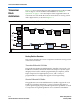
7. Loopback Modes Introduction You can apply several loopback modes to the Stratix® GX block. The main forms of loopback are as follows: ■ ■ ■ Serial loopback Parallel loopback Reverse serial loopback Loopback refers to feeding the data from the transmitter directly to the receiver. Reverse loopback refers to feeding the data from the receiver directly to the transmitter. Serial loopback and parallel loopback feed data from the transmitter block to the receiver.
Parallel Loopback Figure 7–1. Stratix GX Block in Serial Loopback Mode BIST PRBS Verifier Word Aligner Deserializer BIST Incremental Verifier Channel Aligner Rate Matcher Clock Recovery Unit Serializer 8B/10B Encoder Active Path Byte Serializer Byte Deserializer Phase Compensation FIFO Phase Compensation FIFO BIST Generator BIST PRBS Generator Non-Active Path Parallel Loopback 8B/10B Decoder Figure 7–2 shows the data path for parallel loopback.
Loopback Modes Figure 7–2. Stratix GX Block in Parallel Loopback Mode BIST PRBS Verifier Word Aligner Deserializer BIST Incremental Verifier Channel Aligner Rate Matcher Clock Recovery Unit Serializer Active Path Non-Active Path Reverse Serial Loopback 8B/10B Encoder 8B/10B Decoder Byte Serializer Byte Deserializer Phase Compensation FIFO Phase Compensation FIFO BIST Generator BIST PRBS Generator Figure 7–3 shows the data path for reverse serial loopback.
Reverse Serial Loopback Figure 7–3.
8. Stratix GX Built-In Self Test (BIST) Introduction Each Stratix® GX channel in the gigabit transceiver block contains embedded built-in self test (BIST) circuitry, which is available for quick device verification. The BIST circuitry consists of a data generator that resides in the transmitter channel and a verifier that resides in the receiver channel. Figure 8–1 shows a simplified block diagram of the BIST circuitry. Figure 8–1.
Pattern Generator Figure 8–2.
Stratix GX Built-In Self Test (BIST) PRBS mode is enabled when the PRBS option is enabled in the Quartus II software. The 8b-10b encoder/decoder is bypassed automatically in this mode. You can use PRBS generation to test the functionality of both the transmitter and receiver, to test if the BIST verifier is enabled, or to measure the quality of the transmission medium. The advantage of using a PRBS data stream is that the randomness yields an environment that stresses the transmission medium.
Pattern Generator deterministic data dependant components are masked out. However, for more accurate measurements, use a TIA or some type of jitter separation software to break down the random and deterministic components. High-frequency mode is also useful when trying to characterize the high-frequency losses in the time domain.
Stratix GX Built-In Self Test (BIST) Low-frequency mode is enabled when you select the SELF_ option 3 in the Quartus II software under what self test mode do you want to use? You must enable the 8b/10b encoder to generate the high-frequency pattern. If it is disabled, an 8'b11111100 character is sent instead of the 10'b0011111000 or 10'b1100000111 characters. Mix-Frequency Mode Generator In mix-frequency mode, the BIST generator transmits a K28.
Pattern Verifier Be sure you do not use the rx_apllreset signal because the re-training process of the CRU might cause false errors. A reference design is included in “Design Examples” on page 8–7. Incremental Mode Verifier In the incremental mode, the BIST generator transmits the data pattern in the following sequence: K28.5 (comma), K27.7 (SOF), Data (00-FF incremental), K28.0, K28.1, K28.2, K28.3, K28.4, K28.6, K28.7, K23.7, K30.7, K29.7 (EOF), and repeat.
Stratix GX Built-In Self Test (BIST) Design Examples The purpose of these design examples are to show how to instantiate and operate the various BIST modes in Stratix GX devices.
Design Examples input input output output output output output output inclk; rx_in; coreclk_out; tx_out; rx_bisterr; rx_bistdone; rx_clkout; reset; wire wire assign assign reset_wire; VCC; reset = reset_wire; VCC = 1; //Altgxb Instantiation//////////////////////////// PRBS_BIST PRBS_BIST_inst( .inclk(inclk), .rx_in(rx_in), .rx_slpbk(VCC), .rxdigitalreset(reset_wire), .coreclk_out(coreclk_out), .rx_bistdone(rx_bistdone), .rx_bisterr(rx_bisterr), .rx_clkout(rx_clkout), .
Stratix GX Built-In Self Test (BIST) endmodule altgxb Instantiation (PRBS_BIST.
Design Examples .tx_out (sub_wire0), .coreclk_out (sub_wire1), .rx_clkout (sub_wire2), .rx_bistdone (sub_wire3), .rx_bisterr (sub_wire4)); defparam altgxb_component.force_disparity_mode = "OFF", altgxb_component.channel_width = 20, altgxb_component.pll_inclock_period = 6400, altgxb_component.use_symbol_align = "ON", altgxb_component.rx_ppm_setting = 1000, altgxb_component.pll_bandwidth_type = "LOW", altgxb_component.dwidth_factor = 2, altgxb_component.number_of_channels = 1, altgxb_component.
Stratix GX Built-In Self Test (BIST) altgxb_component.data_rate = 3125, altgxb_component.align_pattern = "P1111111111", altgxb_component.use_rx_cruclk = "OFF", altgxb_component.number_of_quads = 1; endmodule Results A quick method for verifying whether the BIST verification passes or fails is to use the SignalTap® II logic analyzer in the Quartus® II software.
Design Examples Figure 8–5.
Stratix GX Built-In Self Test (BIST) .coreclk_out(coreclk_out), .rx_bistdone(rx_bistdone), .rx_bisterr(rx_bisterr), .rx_clkout(rx_clkout), .tx_out(tx_out)); reset_mod reset_mod_inst( .clk(inclk), .reset(reset_wire)); endmodule Reset Module Design (reset_mod.
Design Examples input input input input output output output output output [0:0] [0:0] [0:0] [0:0] [0:0] [0:0] [0:0] [0:0] [0:0] inclk; rx_in; rx_slpbk; rxdigitalreset; tx_out; coreclk_out; rx_clkout; rx_bistdone; rx_bisterr; wire [0:0] sub_wire0; wire [0:0] sub_wire1; wire [0:0] sub_wire2; wire wire wire wire wire wire wire [0:0] sub_wire3; [0:0] sub_wire4; [0:0] tx_out = sub_wire0[0:0]; [0:0] coreclk_out = sub_wire1[0:0]; [0:0] rx_clkout = sub_wire2[0:0]; [0:0] rx_bistdone = sub_wire3[0:0]; [0:0] rx
Stratix GX Built-In Self Test (BIST) altgxb_component.lpm_type = "altgxb", altgxb_component.use_fifo_mode = "ON", altgxb_component.use_vod_ctrl_signal = "OFF", altgxb_component.equalizer_ctrl_setting = 0, altgxb_component.use_auto_bit_slip = "ON", altgxb_component.use_rate_match_fifo = "OFF", altgxb_component.signal_threshold_select = 80, altgxb_component.self_test_mode = 1, altgxb_component.use_double_data_mode = "ON", altgxb_component.use_preemphasis_ctrl_signal = "OFF", altgxb_component.
Design Examples Figure 8–6. SignalTap II Results for PRBS BIST Test Design (Resets the Verifier) (2) (3) (1) rx_bistdone signifies that the verification cycle is complete resets the verifier rx_bisterr remains low, signifying no bit errors Design 3: High-Frequency Transmitter Generator Design This design shows how to instantiate the altgxb megafunction in the high-frequency BIST mode. Because this design consists only of a single transmitter design, only the altgxb instantiation is shown.
Stratix GX Built-In Self Test (BIST) , , = 1000, altgxb_component.pll_inclock_period = 6250, altgxb_component.pll_bandwidth_type = "LOW" altgxb_component.dwidth_factor = 2, altgxb_component.number_of_channels = 1 altgxb_component.vod_ctrl_setting altgxb_component.use_self_test_mode = "ON", altgxb_component.lpm_type = "altgxb", altgxb_component.use_fifo_mode = "ON", altgxb_component.use_vod_ctrl_signal = "OFF", altgxb_component.self_test_mode = 2, altgxb_component.
Design Examples Figure 8–7. High-Frequency BIST Measured on tx_out[] Design 4: Low-Frequency Transmitter Generator Design This design shows how to instantiate the altgxb megafunction in the low-frequency BIST mode. Because this design consists only of a single transmitter design, only the altgxb instantiation is shown. The top level simply consists of calling the megafunction instance. altgxb Instantiation (low_freq_BIST.
Stratix GX Built-In Self Test (BIST) altgxb altgxb_component ( inclk (inclk), .tx_out (sub_wire0), .coreclk_out (sub_wire1)); defparam altgxb_component.force_disparity_mode = "OFF", altgxb_component.channel_width = 16, altgxb_component.pll_inclock_period = 6250, altgxb_component.pll_bandwidth_type = "LOW", altgxb_component.dwidth_factor = 2, altgxb_component.number_of_channels = 1, altgxb_component.vod_ctrl_setting = 1000, altgxb_component.use_self_test_mode = "ON", altgxb_component.
Design Examples Figure 8–8. Low-Frequency BIST Measured on tx_out[] Design 5: Mix-Frequency Transmitter Generator Design The mix-frequency transmitter generator design shows how to instantiate the altgxb megafunction in the mix-frequency BIST mode. Because this design consists only of a single transmitter design, only the altgxb instantiation is shown. The top level simply consists of calling the megafunction instance. altgxb Instantiation (mix_freq_BIST.
Stratix GX Built-In Self Test (BIST) altgxb altgxb_component ( inclk (inclk), .tx_out (sub_wire0), .coreclk_out (sub_wire1)); defparam altgxb_component.force_disparity_mode = "OFF", altgxb_component.channel_width = 16, altgxb_component.pll_inclock_period = 6250, altgxb_component.pll_bandwidth_type = "LOW", altgxb_component.dwidth_factor = 2, altgxb_component.number_of_channels = 1, altgxb_component.vod_ctrl_setting = 1000, altgxb_component.use_self_test_mode = "ON", altgxb_component.
Design Examples Figure 8–9.
9. Reset Control & Power Down Introduction Stratix® GX transceivers offer multiple reset signals to control separate ports of the transceiver channels and transceiver blocks, as shown in Figure 9–1. The Quartus® II software sets each unused channel to a power-down mode to reduce power consumption. Figure 9–1.
USER Reset & Enable Signals The rxanalogreset signal is a power-down signal and only powers down the receiver. The analog circuitry is powered down when the rxanalogreset signal goes high. Although there is no specific requirement on the duration of the rxanalogreset signal, Altera lab experiments have shown that 1 ms is a safe value.
Reset Control & Power Down In 16-bit or 20-bit mode, asserting rxdigitalreset causes the recovered clock or the slow clock to reset. The slow clock is divided down by the deserialization factor from rx_clkout. Altera recommends synchronizing rxdigitalreset to the FPGA or the logic array clock.
Recommended Resets Recommended Resets The following reset recommendations help guard against potential initialization issues during the training of the transmitter PLL and receiver PLLs. The counters that you specify in the recommendations filter out any high frequency effects to ensure that the lock signals are stable before releasing the subsequent reset signals. This action adds to the robustness of the reset sequence.
Reset Control & Power Down Figure 9–3 shows a situation in which you must reset both the transmitter and receiver channels. Figure 9–3.
Recommended Resets The waveform in Figure 9–4 shows the functionality of the receiver and transmitter reset sequence shown in Figure 9–3. The pll_areset signal resets the entire transceiver block, including both the analog and digital portions of the transmitter and receiver (see Table 9–1). After the pll_areset signal goes low, the controller waits until the transmitter PLL is stable (pll_locked = 1’b1) before sending the tx_digitalreset and rx_analogreset low.
Reset Control & Power Down Design Example 1 This design example shows inclk as the input reference clock and the transmit parallel clock and rx_coreclk as the receive parallel clock. The design example has the following constraints: ■ ■ ■ ■ ■ ■ If your design requirements are different from the examples, use the flow charts and waveforms for each configuration as design guidelines. The design example requires a reset controller that generates a sync_reset (synchronous reset) for the entire system.
Recommended Resets receive_digitalreset, pll_locked, rx_freqlocked, pll_areset, txdigitalreset, rxanalogreset, rxdigitalreset ); input inclk; //GXB input reference clock input rx_coreclk;//Receive recovered clock input sync_reset; //Input: synchronous reset from the system input async_reset; //Input: async reset from system input transmit_digitalreset; //Input: Reset only the transmit digital section input receive_digitalreset; //Input : Reset the receiver section input rx_freqlocked; //rx_freqlocked sign
Reset Control & Power Down always @ (posedge inclk or posedge async_reset) begin if (async_reset) begin rxdigitalreset_inclk <= 1'b1; rxanalogreset_inclk <= 1'b1; txdigitalreset <= 1'b1; pll_areset <= 1'b1; waitstate_timer <= WAITSTATE_TIMER_VALUE; state <= STROBE_TXPLL_LOCKED; end else case (state) IDLE: if (sync_reset) //Synchronous Reset can be asserted in IDLE state (After reset seq has finished) begin rxdigitalreset_inclk <= 1'b1; rxanalogreset_inclk <= 1'b1; txdigitalreset <= 1'b1; pll_areset <= 1'b1
Recommended Resets state <= STROBE_TXPLL_LOCKED; rxdigitalreset_inclk <= 1'b1; rxanalogreset_inclk <= 1'b1; txdigitalreset <= 1'b1; pll_areset <= 1'b0; end STABLE_TX_PLL: if (sync_reset) //Synchronous Reset can be asserted in IDLE state (After reset seq has finished) begin rxdigitalreset_inclk <= 1'b1; rxanalogreset_inclk <= 1'b1; txdigitalreset <= 1'b1; pll_areset <= 1'b1; state <= STROBE_TXPLL_LOCKED; end else if (rx_freqlocked) begin state <= WAIT_STATE; waitstate_timer <= waitstate_timer 1'b1 ; rxdigit
Reset Control & Power Down pll_areset <= 1'b0; end else begin waitstate_timer <= waitstate_timer - 1'b1; rxdigitalreset_inclk<= 1'b1; rxanalogreset_inclk <= 1'b0; txdigitalreset<= 1'b0; pll_areset <= 1'b0; state <= WAIT_STATE; end end else begin rxdigitalreset_inclk<= 1'b1; rxanalogreset_inclk <= 1'b0; txdigitalreset<= 1'b0; pll_areset <= 1'b0; waitstate_timer <= WAITSTATE_TIMER_VALUE; state <= STABLE_TX_PLL; end default: state = IDLE; endcase end /*synchronizing the rxdigitalreset to recovered clock domai
Recommended Resets else begin rxdigitalreset_rx_coreclk_Q <= rxdigitalreset_inclk; rxdigitalreset <= rxdigitalreset_rx_coreclk_Q; end end endmodule Design Example 2 The following design example shows inclk as the input reference clock and the transmit parallel clock and rx_clkout as the receive parallel clock.
Reset Control & Power Down Transmit and Receive : Both used Datapath : Single Width(8/10 bits) or Double Width (16/20 bits) receive parallel clock: rx_clkout Functional Mode :'Any' RX PLL CRU : Train RX PLL CRU with TX PLL ouput clock ***************************************************************/ `timescale 1ns/10ps module reset_seq_tx_train_rx_rx_clkout ( rx_clkout, inclk, sync_reset, async_reset, transmit_digitalreset, receive_digitalreset, pll_locked, rx_freqlocked, pll_areset, txdigitalreset, rxanal
Recommended Resets reg rxdigitalreset_rx_clkout_Q; reg rxanalogreset_rx_clkout_Q; parameter parameter parameter parameter IDLE = 3'b000; STROBE_TXPLL_LOCKED = 3'b001; STABLE_TX_PLL = 3'b010; WAIT_STATE = 3'b011; //Parameter value of T (2ms)based on the fastest clock (or 3.
Reset Control & Power Down begin rxdigitalreset_inclk <= 1'b1; rxanalogreset_inclk <= 1'b1; txdigitalreset <= 1'b1; pll_areset <= 1'b1; state <= STROBE_TXPLL_LOCKED; end //Wait untill the TXPLL is locked to inclk and TX PLL has a stable output clock which is also fed to RX CRU else if (pll_locked) begin state <= STABLE_TX_PLL; rxdigitalreset_inclk<= 1'b1; rxanalogreset_inclk <= 1'b0; txdigitalreset<= 1'b0; pll_areset <= 1'b0; end else begin state <= STROBE_TXPLL_LOCKED; rxdigitalreset_inclk <= 1'b1; rxanal
Recommended Resets pll_areset <= 1'b1; state <= STROBE_TXPLL_LOCKED; end else if(rx_freqlocked) //Condition to have rx_freqlocked signal a stable high and should not bounce around begin //Decrement a Timer of 2ms (Refer Stratix GX Datasheet for accurate value)after rx_freqlocked is asserted //This time is given to ensure the recovered clock to be stable (No freq variations) and is locked to incomming data if(waitstate_timer == 0) begin state <= IDLE; rxdigitalreset_inclk<= 1'b0; rxanalogreset_inclk <= 1'b0
Reset Control & Power Down pld clock domain(Generic name, can be any clock name) as read clock.
Recommended Resets Figure 9–5. Receiver & Transmitter With No Train Receiver CRU Option Transmit and Receive (Duplex) with Train RX CRU with TXPLL output clock option disabled data path width Receive Parallel Clock Single Width (8/10) Transmit Parallel Clock rx_clkout rx_coreclk tx_coreclk Double Width (16/20) Transmit Parallel Clock Receive Parallel Clock inclk rx_clkout tx_coreclk inclk Figure 9–6 shows the transmitter reset sequence.
Reset Control & Power Down Figure 9–6. Transmitter Reset Sequence Start async_reset or sync_reset pll_areset = high txdigitalreset = high pll_areset = low txdigitalreset = high pll_locked = high NO pll_areset = low txdigitalreset = high YES YES pll_areset = low txdigitalreset = low transmit_digitalreset = high NO The waveform in Figure 9–7 shows the functionality of the transmitter reset sequence shown in Figure 9–6.
Recommended Resets Figure 9–7. Transmitter Reset Sequence Waveform Reset Signals 1 2 pll_areset 4 tx_digitalreset Stable TXPLL Clock Output Status 3 pll_locked Figure 9–8 shows the receiver reset sequence.
Reset Control & Power Down Figure 9–8. Receiver Reset Sequence Start pll_areset or sync_reset rxanologreset = high rxdigitalreset = high rxanalogreset = low rxdigitalreset = low rxanalogreset = low rxdigitalreset = high NO receive_digitalreset = high rxfreqlocked = high NO YES rxanalogreset = low rxdigitalreset = high YES rxanalogreset = low rxdigitalreset = high NO waitstate_timer = 0 YES The waveform in Figure 9–9 shows the functionality of the receiver reset sequence shown in Figure 9–8.
Recommended Resets Figure 9–9. Receiver Reset Sequence Waveform Reset Signals 1 2 rx_analogreset 4 rx_digitalreset Stable Recovered Clock Output Status 3 rx_freqlocked Trx_freqlock2phaselock Design Example 1 This design example shows inclk as the transmit PLL input reference clock and the transmit parallel clock, rx_cruclk as the receive CRU input reference clock, and rx_coreclk as the receive parallel clock.
Reset Control & Power Down Contacting Altera ================= We have made every effort to ensure that this design example works correctly. If you have a question that is not answered by the information, please contact Altera Support. **************************************************************** Reset Sequence for the ALTGXB.
Recommended Resets output output output output reg reg reg reg reg rxdigitalreset;//GXB Receive digital reset rxanalogreset;//Receive power down signal txdigitalreset; //GXB transmit digital reset pll_areset;//GXB power down signal rxdigitalreset; txdigitalreset; pll_areset; [2:0] state; rxdigitalreset_rx_cruclk; reg rxdigitalreset_rx_coreclk_Q; reg rxanalogreset; parameter IDLE = 3'b000; parameter STROBE_TXPLL_LOCKED = 3'b001; parameter STABLE_TX_PLL = 3'b010; //Parameter value of T (2ms)based on the
Reset Control & Power Down STROBE_TXPLL_LOCKED: if (sync_reset) //Synchronous Reset can be asserted in IDLE state (After reset seq has finished) begin txdigitalreset <= 1'b1; pll_areset <= 1'b1; state <= STROBE_TXPLL_LOCKED; end //Wait untill the TXPLL is locked to inclk and TX PLL has a stable output clock which is also fed to RX CRU else if (pll_locked) begin state <= STABLE_TX_PLL; txdigitalreset<= 1'b0; pll_areset <= 1'b0; end else begin state <= STROBE_TXPLL_LOCKED; txdigitalreset <= 1'b1; pll_areset
Recommended Resets begin waitstate_timer <= waitstate_timer; if(receive_digitalreset) rxdigitalreset_rx_cruclk <= 1'b1; else rxdigitalreset_rx_cruclk <= 1'b0; end else begin waitstate_timer <= waitstate_timer - 1'b1; rxdigitalreset_rx_cruclk <= 1'b1; end end else begin rxdigitalreset_rx_cruclk <= 1'b1; waitstate_timer <= WAITSTATE_TIMER_VALUE; end end end /*synchronizing the rxdigitalreset to If rxdigitalreset is used for Receive synchronization is needed because internally the rxdigitalreset is only cloc
Reset Control & Power Down end end endmodule Design Example 2 This design example shows inclk as the transmit PLL input reference clock and transmit parallel clock, rx_cruclk as the receive CRU input reference clock, and rx_clkout as the receive parallel clock. This design example has the following constraints: ■ ■ ■ ■ ■ ■ If your design requirements are different from the examples, use the flow charts and waveforms for each configuration as design guidelines.
Recommended Resets ***************************************************************/ `timescale 1ns/10ps module reset_seq_tx_rx_rx_cruclk_rx_clkout ( rx_clkout, inclk, rx_cruclk, sync_reset, async_reset, transmit_digitalreset, receive_digitalreset, pll_locked, rx_freqlocked, pll_areset, txdigitalreset, rxanalogreset, rxdigitalreset ); input inclk; //GXB input reference clock input rx_cruclk; //Receive GXB input reference clock input rx_clkout;//Receive recovered clock input sync_reset; //Input: synchronou
Reset Control & Power Down parameter STABLE_TX_PLL = 3'b010; //Parameter value of T (2ms)based on the fastest clock (or 3.
Recommended Resets begin state <= STROBE_TXPLL_LOCKED; txdigitalreset <= 1'b1; pll_areset <= 1'b0; end STABLE_TX_PLL: if (sync_reset) //Synchronous Reset can be asserted in IDLE state (After reset seq has finished) begin txdigitalreset <= 1'b1; pll_areset <= 1'b1; state <= STROBE_TXPLL_LOCKED; end else state <= IDLE; default: state = IDLE; endcase end //Receive Reset Sequence always @(posedge rx_cruclk or posedge pll_areset) if(pll_areset) begin rxanalogreset <= 1'b1; rxdigitalreset_rx_cruclk <= 1'b1; wait
Reset Control & Power Down rxdigitalreset_rx_cruclk <= 1'b1; end end else begin rxdigitalreset_rx_cruclk <= 1'b1; waitstate_timer <= WAITSTATE_TIMER_VALUE; end end end /*synchronizing the rxdigitalreset to recovered clock domain If rxdigitalreset is only used for Receive GXB, then the following synchronization is not needed because internally the rxdigitalreset is synchronized to recovered clock (rx_clkout).
Recommended Resets Receiver Reset The configurations and design examples in this section describe how to implement a reset sequence for the receiver channels. This section describes the reset sequence only. Each design example lists the constraints specific to the example to help you understand the design parameters and limitations. You may want to add additional escape states and other system-specific features in your design.
Reset Control & Power Down Figure 9–11.
Recommended Resets f See the Stratix GX FPGA Family data sheet for the value of Trx_freqlock2phaselock. Figure 9–12.
Reset Control & Power Down /* Copyright (c) Altera Corporation, 2004. This file may contain proprietary and confidential information of Altera Corporation Contacting Altera ================= We have made every effort to ensure that this design example works correctly. If you have a question that is not answered by the information, please contact Altera Support. **************************************************************** Reset Sequence for the ALTGXB.
Recommended Resets output rxdigitalreset;//GXB Receive digital reset output rxanalogreset;//Receive power down signal output pll_areset;//GXB power down signal reg rxdigitalreset; wire rxanalogreset; reg reg reg reg pll_areset; [2:0] state; rxdigitalreset_inclk; rxanalogreset_inclk; reg rxdigitalreset_rx_coreclk_Q; reg rxanalogreset_rx_coreclk_Q; parameter parameter parameter parameter IDLE = 3'b000; STROBE_TXPLL_LOCKED = 3'b001; STABLE_TX_PLL = 3'b010; WAIT_STATE = 3'b011; //Parameter value of T (2ms)
Reset Control & Power Down begin rxdigitalreset_inclk <= 1'b0; rxanalogreset_inclk <= 1'b0; pll_areset <= 1'b0; state <= IDLE; end STROBE_TXPLL_LOCKED: if (sync_reset) //Synchronous Reset can be asserted in IDLE state (After reset seq has finished) begin rxdigitalreset_inclk <= 1'b1; rxanalogreset_inclk <= 1'b1; pll_areset <= 1'b1; state <= STROBE_TXPLL_LOCKED; end //Wait untill the TXPLL is locked to inclk and TX PLL has a stable output clock which is also fed to RX CRU else if (pll_locked) begin state <=
Recommended Resets rxanalogreset_inclk <= 1'b0; pll_areset <= 1'b0; end WAIT_STATE: if (sync_reset) //Synchronous Reset can be asserted in IDLE state (After reset seq has finished) begin rxdigitalreset_inclk <= 1'b1; rxanalogreset_inclk <= 1'b1; pll_areset <= 1'b1; state <= STROBE_TXPLL_LOCKED; end else if(rx_freqlocked) //Condition to have rx_freqlocked signal a stable high and should not bounce around begin //Decrement a Timer of 2ms (Refer Stratix GX Datasheet for accurate value)after rx_freqlocked is a
Reset Control & Power Down /*synchronizing the rxdigitalreset to recovered clock domain If rxdigitalreset is used for Receive GXB, then this synchronization is needed because internally the rxdigitalreset is synchronized to recovered clock (rx_clkout).
Recommended Resets ■ ■ In this example, whenever the rx_freqlocked signal toggles the rxdigitalreset, the receiver’s digital circuit is reset. However, you can make changes to the design to avoid this if, for example, you want to debug your design without the core being reset. If you plan to use REFCLKB pins in your design, see Appendix C, REFCLKB Pin Constraints for information about the effects of analog resets (pll_arest, rx_analogreset). /* Copyright (c) Altera Corporation, 2004.
Reset Control & Power Down input sync_reset; input async_reset; //Input: synchronous reset from the system //Input: async reset from system input receive_digitalreset; //Input : Reset the receiver section input rx_freqlocked; //rx_freqlocked signal from receive; Transition from 'lock to reference clock mode' to 'lock to data mode' input pll_locked; // Transmit PLL of GXB locked output rxdigitalreset;//GXB Receive digital reset output rxanalogreset;//Receive power down signal output pll_areset;//GXB powe
Recommended Resets rxanalogreset_inclk <= 1'b1; pll_areset <= 1'b1; waitstate_timer <= WAITSTATE_TIMER_VALUE; state<= STROBE_TXPLL_LOCKED; end else begin rxdigitalreset_inclk <= 1'b0; rxanalogreset_inclk <= 1'b0; pll_areset <= 1'b0; state <= IDLE; end STROBE_TXPLL_LOCKED: if (sync_reset) //Synchronous Reset can be asserted in IDLE state (After reset seq has finished) begin rxdigitalreset_inclk <= 1'b1; rxanalogreset_inclk <= 1'b1; pll_areset <= 1'b1; state <= STROBE_TXPLL_LOCKED; end //Wait untill the TXPL
Reset Control & Power Down waitstate_timer <= waitstate_timer 1'b1 ; rxdigitalreset_inclk<= 1'b1; rxanalogreset_inclk <= 1'b0; pll_areset <= 1'b0; end else begin state <= STABLE_TX_PLL; rxdigitalreset_inclk<= 1'b1; rxanalogreset_inclk <= 1'b0; pll_areset <= 1'b0; end WAIT_STATE: if (sync_reset) //Synchronous Reset can be asserted in IDLE state (After reset seq has finished) begin rxdigitalreset_inclk <= 1'b1; rxanalogreset_inclk <= 1'b1; pll_areset <= 1'b1; state <= STROBE_TXPLL_LOCKED; end else if(rx_freq
Recommended Resets pll_areset <= 1'b0; waitstate_timer <= WAITSTATE_TIMER_VALUE; state <= STABLE_TX_PLL; end default: state = IDLE; endcase end /*synchronizing the rxdigitalreset to recovered clock domain If rxdigitalreset is only used for receive GXB, synchronization is redundant because internally the rxdigitalreset is synchronized to the recovered clock (rx_clkout).
Reset Control & Power Down The difference in this configuration from the configuration in “Receive CRU With Transmit PLL Output Clock Option Enabled” on page 9–32 is that receive CRU is trained by the input pin rx_cruclk. Figure 9–13 shows the receive-only configuration with clock options disabled. Figure 9–13.
Recommended Resets ■ If you plan to use REFCLKB pins in your design, see Appendix C, REFCLKB Pin Constraints for information about the effects of analog resets (pll_arest, rx_analogreset). /* Copyright (c) Altera Corporation, 2004. This file may contain proprietary and confidential information of Altera Corporation Contacting Altera ================= We have made every effort to ensure that this design example works correctly.
Reset Control & Power Down output rxdigitalreset;//GXB Receive digital reset output rxanalogreset;//Receive power down signal reg rxdigitalreset; reg rxdigitalreset_rx_cruclk; reg rxdigitalreset_rx_coreclk_Q; reg rxanalogreset; //Parameter value of T (2ms)based on the fastest clock (or 3.
Recommended Resets begin waitstate_timer <= waitstate_timer - 1'b1; rxdigitalreset_rx_cruclk <= 1'b1; end end else begin rxdigitalreset_rx_cruclk <= 1'b1; waitstate_timer <= WAITSTATE_TIMER_VALUE; end end end /*synchronizing the rxdigitalreset to If rxdigitalreset is used for Receive synchronization is needed because internally the rxdigitalreset is only clock (rx_clkout).
Reset Control & Power Down Design Example 2 This design example shows a receive-only configuration with rx_cruclk as the receive CRU input reference clock and rx_clkout as the receive parallel interface clock. This design example has the following constraints: ■ ■ ■ ■ ■ ■ If your design requirements are different from the examples, use the flow charts and waveforms for each configuration as design guidelines.
Recommended Resets `timescale 1ns/10ps module reset_seq_rx_rx_cruclk_rx_clkout ( rx_clkout, rx_cruclk, sync_reset, async_reset, receive_digitalreset, rx_freqlocked, rxanalogreset, rxdigitalreset ); input rx_cruclk; //Receive GXB input reference clock input rx_clkout;//Receive recovered clock input sync_reset; //Input: synchronous reset from the system input async_reset; //Input: async reset from system input receive_digitalreset; //Input : Reset the receiver section input rx_freqlocked; //rx_freqlocked si
Reset Control & Power Down end else begin if(sync_reset) begin rxanalogreset <= 1'b1; rxdigitalreset_rx_cruclk<= 1'b1; waitstate_timer <= WAITSTATE_TIMER_VALUE; end else begin rxanalogreset <= 1'b0; if (rx_freqlocked) begin if(waitstate_timer == 0) begin waitstate_timer <= waitstate_timer; if(receive_digitalreset) rxdigitalreset_rx_cruclk <= 1'b1; else rxdigitalreset_rx_cruclk <= 1'b0; end else begin waitstate_timer <= waitstate_timer - 1'b1; rxdigitalreset_rx_cruclk <= 1'b1; end end else begin rxdigitalre
Recommended Resets always @(posedge rx_clkout or posedge async_reset) if(async_reset) begin rxdigitalreset_rx_clkout_Q <= 1'b1; rxdigitalreset <= 1'b1; end else begin if(receive_digitalreset) begin rxdigitalreset_rx_clkout_Q <= 1'b1; rxdigitalreset <= 1'b1; end else begin rxdigitalreset_rx_clkout_Q <= rxdigitalreset_rx_cruclk; rxdigitalreset <= rxdigitalreset_rx_clkout_Q; end end endmodule Transmitter Reset The configurations and design examples in this section show how to implement a reset sequence for t
Reset Control & Power Down Figure 9–14. Transmitter Only Clock Options Transmit ONLY data path width Single Width (8/10) Double Width (16/20) Transmit Parallel Clock tx_coreclk inclk tx_coreclk inclk Figure 9–15 shows a situation where only the transmitter channel requires a reset sequence. Figure 9–15.
Recommended Resets The waveform in Figure 9–16 shows the functionality of the transmitter reset sequence shown in Figure 9–15. As described in Table 9–1 on page 9–3, the pll_areset resets the entire transceiver block, including both the analog and digital portions of the transmitter and receiver. After this signal is deasserted, the controller waits until the transmitter PLL is stable (pll_locked = 1'b1) before deasserting tx_digitalreset.
Reset Control & Power Down ■ If you plan to use REFCLKB pins in your design, see Appendix C, REFCLKB Pin Constraints for information about the effects of analog resets (pll_arest, rx_analogreset). /* Copyright (c) Altera Corporation, 2004. This file may contain proprietary and confidential information of Altera Corporation Contacting Altera ================= We have made every effort to ensure that this design example works correctly.
Recommended Resets output txdigitalreset; //GXB transmit digital reset output pll_areset;//GXB power down signal reg txdigitalreset; reg pll_areset; reg [1:0] state; parameter IDLE = 2'b00; parameter STROBE_TXPLL_LOCKED = 2'b01; always @ (posedge inclk or posedge async_reset) begin if (async_reset) begin txdigitalreset <= 1'b1; pll_areset <= 1'b1; state <= STROBE_TXPLL_LOCKED; end else case (state) IDLE: if (sync_reset) //Synchronous Reset can be asserted in IDLE state (After reset seq has finished) begi
Reset Control & Power Down else if (pll_locked) begin state <= IDLE; txdigitalreset <= 1'b0; pll_areset <= 1'b0; end else begin state <= STROBE_TXPLL_LOCKED; txdigitalreset <= 1'b1; pll_areset <= 1'b0; end default: state = IDLE; endcase end endmodule Power Down The Quartus II software automatically selects the power-down feature when you configure the Stratix GX device. All unused transceiver channels and transceiver blocks in a design are powered down to reduce the overall power consumption.
Power Down Table 9–2. I/O Pin States During Power-Down (Part 2 of 2) Operation PMA loop back Transmitter Pins Receiver Pins REFCLKB Pins Rref Pin Serial loop back Tri-state (4) toggle Low (5) — — Reverse serial loop back Transmitter (6) Receiver — — Notes to Table 9–2: (1) (2) (3) (4) (5) (6) Either leave these pins floating or connect n_leg to GXB_GND through a 10-kΩ resistor and connect p_leg to GXB_VCC through a 10-kΩ resistor to improve the device’s immunity to noise.
Appendix A. Data & Control Codes 8B/10B Code This appendix provides information about the data and control codes for the Stratix® GX device. Code Notation The 8B/10B data and control codes are referred to as Dx.y and Kx.y, respectively. The 8-bit byte (H G F E D C B A, where H is the MSB and A is the LSB) is broken up into 2 groups, x and y, where x is the 5 lower bits (E D C B A) and y is the upper 3 bits (H G F). Figure A–1 shows the notation for 3C hexadecimal. Figure A–1.
8B/10B Code Figure A–2. 10-Bit Grouping of 6-Bit & 4-Bit Sub-Blocks 10-Bit Code j h g f i e d c b a 9 8 7 6 5 4 3 2 1 0 4-Bit Block 6-Bit Block The running disparity at the beginning of the 6-bit sub-block is the running disparity at the end of the previous 10-bit code. The running disparity of the 4-bit sub-block is the running disparity of the end of the 6-bit sub-block.
Supported Codes The 8B/10B scheme defines the 12 control codes listed in Table A–1 for synchronization, alignment, and general application purposes. Table A–1. Supported K Codes K Code Octal Value 8-Bit Code HGF_EDCBA 10-Bit Code RDabcdei_fghj 10-Bit Code RD+ abcdei_fghj K28.0 1C 8'b000_11100 10'b001111_0100 10'b110000_1011 K28.1 3C 8'b001_11100 10'b001111_1001 10'b110000_0110 K28.2 5C 8'b010_11100 10'b001111_0101 10'b110000_1010 K28.
8B/10B Code Table A–2. Valid Data Code-Groups (Part 2 of 9) Code-group Name Octet Value Octet Bits HGF EDCBA Current RD- Current RD+ abcdei fghj abcdei fghj D9.0 09 000 01001 100101 1011 100101 0100 D10.0 0A 000 01010 010101 1011 010101 0100 D11.0 0B 000 01011 110100 1011 110100 0100 D12.0 0C 000 01100 001101 1011 001101 0100 D13.0 0D 000 01101 101100 1011 101100 0100 D14.0 0E 000 01110 011100 1011 011100 0100 D15.0 0F 000 01111 010111 0100 101000 1011 D16.
Table A–2. Valid Data Code-Groups (Part 3 of 9) Code-group Name Octet Value Octet Bits HGF EDCBA Current RD- Current RD+ abcdei fghj abcdei fghj D10.1 2A 001 01010 010101 1001 010101 1001 D11.1 2B 001 01011 110100 1001 110100 1001 D12.1 2C 001 01100 001101 1001 001101 1001 D13.1 2D 001 01101 101100 1001 101100 1001 D14.1 2E 001 01110 011100 1001 011100 1001 D15.1 2F 001 01111 010111 1001 101000 1001 D16.1 30 001 10000 011011 1001 100100 1001 D17.
8B/10B Code Table A–2. Valid Data Code-Groups (Part 4 of 9) Code-group Name Octet Value Octet Bits HGF EDCBA Current RD- Current RD+ abcdei fghj abcdei fghj D11.2 4B 010 01011 110100 0101 110100 0101 D12.2 4C 010 01100 001101 0101 001101 0101 D13.2 4D 010 01101 101100 0101 101100 0101 D14.2 4E 010 01110 011100 0101 011100 0101 D15.2 4F 010 01111 010111 0101 101000 0101 D16.2 50 010 10000 011011 0101 100100 0101 D17.2 51 010 10001 100011 0101 100011 0101 D18.
Table A–2. Valid Data Code-Groups (Part 5 of 9) Code-group Name Octet Value Octet Bits HGF EDCBA Current RD- Current RD+ abcdei fghj abcdei fghj D12.3 6C 011 01100 001101 1100 001101 0011 D13.3 6D 011 01101 101100 1100 101100 0011 D14.3 6E 011 01110 011100 1100 011100 0011 D15.3 6F 011 01111 010111 0011 101000 1100 D16.3 70 011 10000 011011 0011 100100 1100 D17.3 71 011 10001 100011 1100 100011 0011 D18.3 72 011 10010 010011 1100 010011 0011 D19.
8B/10B Code Table A–2. Valid Data Code-Groups (Part 6 of 9) Code-group Name Octet Value Octet Bits HGF EDCBA Current RD- Current RD+ abcdei fghj abcdei fghj D13.4 8D 100 01101 101100 1101 101100 0010 D14.4 8E 100 01110 011100 1101 011100 0010 D15.4 8F 100 01111 010111 0010 101000 1101 D16.4 90 100 10000 011011 0010 100100 1101 D17.4 91 100 10001 100011 1101 100011 0010 D18.4 92 100 10010 010011 1101 010011 0010 D19.4 93 100 10011 110010 1101 110010 0010 D20.
Table A–2. Valid Data Code-Groups (Part 7 of 9) Code-group Name Octet Value Octet Bits HGF EDCBA Current RD- Current RD+ abcdei fghj abcdei fghj D14.5 AE 101 01110 011100 1010 011100 1010 D15.5 AF 101 01111 010111 1010 101000 1010 D16.5 B0 101 10000 011011 1010 100100 1010 D17.5 B1 101 10001 100011 1010 100011 1010 D18.5 B2 101 10010 010011 1010 010011 1010 D19.5 B3 101 10011 110010 1010 110010 1010 D20.5 B4 101 10100 001011 1010 001011 1010 D21.
8B/10B Code Table A–2. Valid Data Code-Groups (Part 8 of 9) Code-group Name Octet Value Octet Bits HGF EDCBA Current RD- Current RD+ abcdei fghj abcdei fghj D15.6 CF 110 01111 010111 0110 101000 0110 D16.6 D0 110 10000 011011 0110 100100 0110 D17.6 D1 110 10001 100011 0110 100011 0110 D18.6 D2 110 10010 010011 0110 010011 0110 D19.6 D3 110 10011 110010 0110 110010 0110 D20.6 D4 110 10100 001011 0110 001011 0110 D21.6 D5 110 10101 101010 0110 101010 0110 D22.
Table A–2. Valid Data Code-Groups (Part 9 of 9) Code-group Name Octet Value Octet Bits HGF EDCBA Current RD- Current RD+ abcdei fghj abcdei fghj D16.7 F0 111 10000 011011 0001 100100 1110 D17.7 F1 111 10001 100011 0111 100011 0001 D18.7 F2 111 10010 010011 0111 010011 0001 D19.7 F3 111 10011 110010 1110 110010 0001 D20.7 F4 111 10100 001011 0111 001011 0001 D21.7 F5 111 10101 101010 1110 101010 0001 D22.7 F6 111 10110 011010 1110 011010 0001 D23.
8B/10B Code A–12 Stratix GX Transceiver User Guide Altera Corporation January 2005
Appendix B. Ports & Parameters Input Ports Table B–1 lists the input ports of the Stratix® GX device. Table B–1. Input Ports (Part 1 of 4) Port Name Required Description Comments Input port [NUMBER_OF_QUADS - 1..0] wide. If you use the transmitter PLL, the inclk[] port is required. If you set the OPERATION_MODE parameter to TX or DUPLEX, the inclk[] port is required. inclk[] See Transceiver block comments transmitter PLL reference input clock.
Input Ports Table B–1. Input Ports (Part 2 of 4) Port Name Required Description Comments rx_enacdet[] No Enables alignment to the programmed pattern. Input port [NUMBER_OF_CHANNELS 1..0] wide. If you enable the rx_enacdet port, the rx_bitslip[] port cannot be connected, and the USE_AUTO_BIT_SLIP parameter must be set to ON. rx_slpbk[] No Serial loopback input. Dynamically enables serial loopback from the transceiver block transmitter to the transceiver block receiver in the same channel.
Table B–1. Input Ports (Part 3 of 4) Port Name Required Description Comments rx_locktodata[] No Control signal for transceiver block receiver PLL to lock the received data. Input port [NUMBER_OF_CHANNELS 1..0] wide. The rx_locktodata[] port can overwrite the rx_locktorefclk[] port. tx_in[] Yes Transceiver block transmitter channel data input port. Input port [CHANNEL_WIDTH * NUMBER_OF_CHANNELS - 1..0] wide.
Input Ports Table B–1. Input Ports (Part 4 of 4) Port Name tx_vodctrl[] Required No tx_preemphasisctrl[] No Description 3-bit control signal that dynamically specifies the Voltage Output Differential (VOD) control settings. 3-bit control signal that dynamically specifies the preemphasis settings. Comments Input port [NUMBER_OF_CHANNELS * 3 1..0] wide.
Output Ports Table B–2 lists the output ports of the Stratix GX device. Table B–2. Output Ports (Part 1 of 4) Port Name Required Description Comments pll_locked[] No Gives the status of the transceiver block transmitter PLL. Output port [NUMBER_OF_QUADS - 1..0] wide. The pll_locked port is available only when the transceiver block transmitter PLL is used. The signal achieves lock status within several clock cycles in simulation.
Output Ports Table B–2. Output Ports (Part 2 of 4) Port Name Required Description Comments rx_clkout[] No Output clock from the transceiver block receiver channel. Output port [NUMBER_OF_CHANNELS 1..0] wide. If you set the USE_RATE_MATCH_FIFO parameter to ON and the CLK_OUT_MODE_REFERENCE parameter is set to ON, the rx_clkout[] port is the PLL reference clock with the period PLL_INCLOCK_PERIOD / DATA_RATE) * CHANNEL_WIDTH.
Table B–2. Output Ports (Part 3 of 4) Port Name Required Description Comments rx_freqlocked[] No Indicates whether transceiver block receiver channel is locked to the data mode in the rx_in[] port. Output port [NUMBER_OF_CHANNELS 1..0] wide. This port is asserted when the GXB receiver PLL moves to lock to the received data mode.
Output Ports Table B–2. Output Ports (Part 4 of 4) Port Name Required Description Comments rx_errdetect[] No Indicates whether the 8B/10B decoder detects an error code. Output port [NUMBER_OF_CHANNELS * DWIDTH_FACTOR - 1..0] wide. If you set the USE_8B_10B_MODE parameter to OFF, the rx_errdetect port is not available. rx_disperr[] No Indicates whether the 8B/10B decoder detects a disparity error. Output port [NUMBER_OF_CHANNELS * DWIDTH_FACTOR - 1..0] wide.
Parameter Descriptions Table B–3 describes the Stratix GX device parameters. Table B–3. Parameter Descriptions (Part 1 of 6) Parameter Type Required Comments OPERATION_MODE String Yes Specifies the operation of the transceiver block transmitter PLL and transceiver block receiver PLL. Values are RX, TX, and DUPLEX. If the PROTOCOL parameter is set to XAUI, then you must set the OPERATION_MODE parameter to DUPLEX. LOOPBACK_MODE String No Specifies the operation of the loopback.
Parameter Descriptions Table B–3. Parameter Descriptions (Part 2 of 6) Parameter Type Required Comments PLL_INCLOCK_PERIOD Integer Yes Specifies, in picoseconds (ps), the period or frequency of the transceiver block transmitter PLL. If omitted, the default is 0. The value of this parameter is used to compute the input clock frequency in MHz; (1 / PLL_INCLOCK_PERIOD) * 1,000,000. When you specify PLL_INCLOCK_PERIOD, the CRU_INCLOCK_PERIOD parameter cannot be used.
Table B–3. Parameter Descriptions (Part 3 of 6) Parameter Type Required Comments RUN_LENGTH Integer No Specifies the maximum run length supported for the incoming data signal. This parameter is ignored if the RUN_LENGTH_ENABLE parameter is turned off. If the deserialization factor is 8, legal values are 4–128, in multiples of four. If the deserialization factor is 10, legal values are 5–160, in multiples of five. If omitted, the default is 0.
Parameter Descriptions Table B–3. Parameter Descriptions (Part 4 of 6) Parameter SELF_TEST_MODE Type Integer Required No Comments Indicates which self test mode to use. Values are 0, 1, 2, 3, or 4. If omitted, the default is 0. This parameter is ignored if the USE_SELF_TEST_MODE parameter is turned off. Use the following settings: Value 0 1 2 3 4 Test PRBS 00-FF, followed by 5 K28.5+ and repeat High frequency pattern, repeat of D21.5- D21.5+ Low frequency pattern, repeat of K28.7- K28.
Table B–3. Parameter Descriptions (Part 5 of 6) Parameter Type Required Comments VOD_CTRL_SETTING Integer No Specifies, in mV, the value of the VO D control signal. Values are 400, 800, 1000, 1200, 1400, 1600. If omitted, the default is 1000. USE_PREEMPHASIS_ CTRL_SIGNAL String No Specifies whether the pre-emphasis control signal is used. If you enable this parameter, the tx_preemphasisctrl port is used and the PREEMPHASIS_CTRL_SETTING parameter is ignored. Values are ON and OFF.
Parameter Descriptions Table B–3. Parameter Descriptions (Part 6 of 6) Parameter Type CONSIDER_INSTANTIATE _TRANSMITTER_PLL String TX_TERMINATION Integer Required No Comments Specifies whether the INSTANTIATE_TRANSMITTER_PLL parameter is turned on. Values are ON and OFF. If omitted, the default is OFF. No Specifies the termination setting on the pin fed by the transceiver block transmitter channel tx_out[] port. Values are 0, 1, 2, or 3. If omitted, the default is 2.
Appendix C. REFCLKB Pin Constraints Known Issues This document discusses issues you might encounter in certain configurations of the Stratix® GX device. These issues are a result of a combination of resource utilization (REFCLKB pins that use Inter Quad (IQ) lines, signals (pllenable, pll_areset, and rxanalogreset), and software modeling. The potential issues for certain configurations are described below: 1.
Known Issues If the design is using the transmitter PLL output to drive any clock into the core (any part of the device), asserting the rxanalogreset signal of all four channels also resets the transmitter PLL and affects the clock that feeds the core logic. This behavior is not modeled in the Quartus II software simulation. Figure C–1 shows an example of a problem configuration using the Stratix GX 25F device. This configuration is also applicable to all devices in the Stratix GX device family.
Quartus II Software Messages The following sections provide details on the feedback provided by the various versions of the Quartus II software when the design contains configurations 1, 2, or 3, described previously. Quartus II Software to Version 3.0 SP2 This version of the Quartus II software allows configurations 1, 2, and 3, and provides no warnings. Because the behavior of the configuration is not modeled, differences in functionality exist between simulations and actual silicon.
Known Issues Quartus II Software Versions 4.0 SP1 & 4.1 For configurations 1, 2, and 3, the Quartus II software versions 4.0 SP1 and 4.1 provide an error message if the resets are used as described in those configurations. Unconstrained flows create a fit that does not have the clock pin reset problem or a no-fit if such a fit cannot be found. Quartus II software versions 4.0 SP1 and 4.1 provide an error message.
■ f Error: XGMII GXB_RX:GXB_RX_a|CUSTOM_RX:CUSTOM_RX_inst|altgxb:altg xb_component|xgm_machine[0] exists in a Quad that has no GXB Transmitters and has GXB Transmitter PLL GXB_RX:GXB_RX_a|CUSTOM_RX:CUSTOM_RX_inst|altgxb:altg xb_component|pll[0], but all the RXANALOGRESET signals are connected. This is not allowed. Refer to recommendation n in the section “Recommendations” on page C–5 if you have an existing design (including the board) and wish to keep the design.
Known Issues The equivalent INI setting is asm_skip_gxb_clock_fanout_restriction = on If you use the INI variable, you are not required to make any changes to the QSF. When you use the QSF setting, the Quartus II software issues a critical warning if you implement any of the configurations (1, 2, or 3). This critical warning message warns that these clock and reset configurations are not modeled in simulation and there will be differences in behavior between functional simulations and actual silicon.
■ You can use the REFCLKB pin on an unused transceiver block to bring in the clock. Altera recommends that you study the IQ routing to ensure that the transceiver block to be used can be reached from the selected REFCLKB pin. It might be possible to use the global clock pin for lower input clock frequencies. If the design requires using more than one transceiver block, there might be some restrictions because of the limited global clock resources.
Known Issues C–8 Stratix GX Transceiver User Guide Altera Corporation January 2005