Operation Manual Medical AlterG Anti-Gravity Treadmill
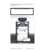
1 Remove AlterG prescription label (part number 102595) below and apply to M320 as shown. Affix prescription label p/n 102595 using double sided tape, 3M Scotch Permanent Glue Stick or equivalent Affix label to front of M320 base frame as shown: Affix prescription label here.
2 AlterG M300 Medical Operations Manual Part Number 102508 Rev D
3 This manual covers operation procedures for the following AlterG products: AlterG Anti-Gravity Treadmill M310 AlterG Anti-Gravity Treadmill M320 NOTE: The following symbol is used throughout this manual to call attention to Warnings, Cautions or operational procedures that may directly affect the safe operation of the AlterG Anti-Gravity Treadmill. Read and understand these instructions and statements before operating the AlterG Anti-Gravity Treadmill.
4 AlterG M300 Medical Operations Manual Part Number 102508 Rev D
5 Contents USER RESPONSIBILITY ..................................................................... 7 AlterG CONTACT INFORMATION ...................................................... 9 INDICATIONS AND CONTRAINDICATIONS FOR USE ................... 11 SAFETY INFORMATION, WARNINGS AND CAUTIONS ................. 13 SECTION 1: INTRODUCTION ........................................................... 17 THINGS TO CONSIDER BEFORE BEGINNING AN EXERCISE PROGRAM . 17 SECTION 2: SETUP AND INSTALLATION ..............
6 AlterG M300 Medical Operations Manual Part Number 102508 Rev D
7 USER RESPONSIBILITY This Product will perform as described in this Operator’s Manual and by accompanying labels and/or inserts, when it is assembled, operated, maintained and repaired in accordance with the instructions provided. This Product must be checked periodically as described in this manual. A defective Product should not be used. Parts that are broken, missing, plainly worn, distorted or contaminated should be replaced immediately.
8 AlterG M300 Medical Operations Manual Part Number 102508 Rev D
9 AlterG CONTACT INFORMATION AlterG Inc. welcomes your inquiries and comments. Professional staff, including physiologists, applications engineers, and customer support specialists are available to assist you with any questions you may have regarding your AlterG Anti-Gravity Treadmill system. AlterG Headquarters: AlterG Address: Telephone: AlterG URL 48438 Milmont Drive Fremont, CA 94538 510-270-5900 www.alter-g.
10 AlterG M300 Medical Operations Manual Part Number 102508 Rev D
11 INDICATIONS AND CONTRAINDICATIONS FOR USE Indications for Use Aerobic conditioning Weight control and reduction Sport specific conditioning programs Gait training in neurologic patients Strengthening and conditioning in older patients Rehabilitation following injury or surgery of the lower extremity Rehabilitation following injury or surgery of the hip, knee, ankle or foot.
12 AlterG M300 Medical Operations Manual Part Number 102508 Rev D
13 SAFETY INFORMATION, WARNINGS AND CAUTIONS Before using the AlterG please familiarize yourself with this manual so that you may operate the AlterG in a safe and effective manner. Instructions may be found throughout this manual, on the control console and on labels applied to the machine. We want your experience with the AlterG to be safe and enjoyable, so please make sure you read and understand this entire manual before operating your system.
14 WARNING: Potentially hazardous situation to be avoided that could result in serious injury or death. Consult with your physician before beginning any exercise program. This is particularly true if you have any of the following: history of heart disease, high blood pressure, diabetes, chronic respiratory disease, elevated cholesterol, if you smoke cigarettes, or have any other chronic disease or physical impairment.
15 Keep the area around the treadmill clear. Make sure you leave at least 2 feet on either side of the AlterG to accommodate bag expansion during inflation. Keep hands away from the bag and frame structure during inflation to avoid pinching. Keep hands away from all moving parts. Wear proper athletic shoes, such as those with rubber or hightraction soles. Do not use shoes with heels or leather soles. Make sure no stones or sharp objects are embedded in the soles.
16 AlterG M300 Medical Operations Manual Part Number 102508 Rev D
17 SECTION 1: INTRODUCTION THINGS TO CONSIDER BEFORE BEGINNING AN EXERCISE PROGRAM CONSULT A PHYSICIAN Anyone considering an exercise program or an increase in activity should consult a physician. If you have cardiovascular disease or there is a history of such disease in your family, are overweight or are not currently involved in an exercise program, it is highly recommended that you follow the guidance of your physician before and during an exercise program or any other increase in physical activity.
18 AlterG M300 Medical Operations Manual Part Number 102508 Rev D
19 SECTION 2: SETUP AND INSTALLATION An AlterG qualified technician will install the AlterG Anti-Gravity Treadmill after delivery. Please make sure that you inspect the AlterG upon delivery for any damage that may have occurred during transportation. Take pictures and immediately report any damage to the shipping company and AlterG. When you sign for the shipment of your AlterG, you are taking responsibility for any damage that may occur before installation.
20 qualified electrician or AlterG if you plan on extending the cord in any way. Make sure you leave at least 24 inches on either side of the AlterG to allow the bag to expand during inflation. Allow 40 inches behind the AlterG to accommodate a user getting in and out of the AlterG system safely. We recommend an area at least 12 feet (3.66 meters) long by 8 feet (2.44 meters) wide to provide adequate space for operation and user access. Also check ceiling height to ensure users won’t hit their heads.
21 SECTION 3: PRINCIPLES OF OPERATION AlterG’s technology was originally conceived as part of an effort to help NASA’s astronauts maintain fitness during prolonged space flight. AlterG pioneered the concept of combining this technology with an advanced pressure regulation system and treadmill into a machine that provides the most effective and comfortable body weight support system available today. PHYSICS & TECHNOLOGY BEHIND THE ALTERG Figure 1.
22 PRESSURE REGULATION SYSTEM AlterG has developed an advanced and very sophisticated pressure regulation system that ensures the AlterG has extremely accurate weight control with good reproducibility between sessions. When you run in the AlterG, the natural bouncing motion of your body changes the shape and volume of the bag.
23 SECTION 4: OPERATING THE ALTERG POWERING UP The AlterG is turned on by operating the switch located on the front cover of the system. Note: Once the power switch is turned on, wait 30 seconds before the subject attempts to use the AlterG. The system requires 30 seconds to run a series of diagnostic tests. The weight control display will show 0 or L and the treadmill display will be blank when the system is ready to be used. Figure 3.
24 STEPPING INTO THE ALTERG Lower the cockpit so it compresses the bag against the treadmill surface (Figure 5). Push it all the way down for ease of entry. Enter from the back and step into the opening in the fabric enclosure. It is fine to step on the fabric as you enter, but make sure that you have no rocks or sharp objects embedded in the soles of your shoes that could mar or damage the bag. ! CAUTION: The AlterG Anti-Gravity Treadmill belt operates like any other conventional treadmill belt.
25 ADJUSTING THE HEIGHT OF THE COCKPIT The cockpit slides up and down on a bearing system and is counterweighted to make it easy to lift. ! CAUTION: Before lifting the cockpit, ensure that the cockpit lock is in the open position, all the way to the left side of its travel. If it is not fully unlocked, it may engage in the lowest position as you lift. See Figure 6. Cockpit lock in open position Figure 5.
26 Cockpit lock in closed or locked position Figure 6. Cockpit Lock Fully Engaged There is a range of heights at which the cockpit can be placed. For greatest freedom of movement, place the tubing that comprises the cockpit slightly below the greater trochanter of the femur. Figure 8 demonstrates this position. Top surface of cockpit slightly below greater trochanter Figure 7.
27 For more support and stability place the cockpit in a higher position. Some users use the iliac crest as a reference point. Pull up on the zipper sewn to the enclosure and align the zipper with the iliac crest as shown in Figure 9. Zipper at level of iliac crest Figure 8. Adjustment of the Cockpit to Align the Zipper with the Iliac Crest You should never attempt to move the cockpit while the fabric enclosure is inflating or when fully inflated.
28 USE OF THE SAFETY LANYARD It is essential that you ALWAYS use the magnetic safety lanyard supplied with the machine. Secure the clip all the way onto your clothing and place the red magnet on the circular locator labeled “Emergency Stop”. The lanyard and magnet serve as a safety switch mechanism. If you become uncomfortable during exercise you can pull or swipe the lanyard to displace the magnet and stop the system.
29 OPERATING THE TREADMILL AND UNWEIGHTING SYSTEM Figure 11. Operating Console All treadmill and pressure functions are controlled from the console. Graphic icons and labels identify button locations and functions. Buttons are touch sensitive and require light pressure to operate.
30 Press START to begin Press PAUSE to pause treadmill Press STOP to end exercise LED’s display % of your full body weight Press + to increase body weight Press - to decrease body weight Figure 12. Left Side Console Controls STEP 1: PREPARATION FOR EXERCISE. Before pressing START, stand still on the surface of the treadmill belt. Do not hold onto or support yourself on any part of the system structure. The system weighs you prior to exercise and the treadmill must support your full body weight.
31 CAUTION: At 40% body weight and lower, you can become unstable if you jump or perform any other activity besides walking or running. Reduce your body weight percentage slowly so you can become accustomed to the new sensation and adjust your gait mechanics accordingly. ! Data display LED indicates current display Speed display Press + to increase, - to decrease speed Select display Press for reverse walking, LED lights Figure 13.
32 Note: Treadmill grade cannot be adjusted greater than 5% if speed is set for less than .5 mph (.8 km/hr). STEP 7: ENDING THE EXERCISE SESSION Return the treadmill to 0% incline before stopping your session. Press the STOP button to end exercise. The treadmill will run through a shutdown routine and the pressure will be released from the inflated enclosure. All exercise information will be cleared from the display.
33 HEART RATE MONITORING HEART RATE MONITOR The AlterG display is designed to receive a user’s heart rate in conjunction with the use of a Polar® (Chest Strap) Heart Rate Monitor.3 Polar chest straps can be purchased at most popular sporting goods stores or online. In order for the screen to correctly display a user’s heart rate, the receiver within the display must obtain a stable heart rate signal from the Polar transmitter.
34 AlterG M300 Medical Operations Manual Part Number 102508 Rev D
35 SECTION 5: LABELS, LOCATIONS, INTERPRETATION Read and understand the labels on the AlterG Anti-Gravity Treadmill. The labels provide information on the operation of the system and should be followed for a safe and enjoyable exercise experience. Should any of the labels become damaged and unreadable, immediately contact AlterG for replacements. The location of the labels is indicated in Figure 14. Refer to the diagram to locate the label being described. Figure 14.
36 Label #1. This label is located on areas of the Anti-Gravity Treadmill frame that present a pinch hazard. Hands or any other part of the body should not be placed in these areas during operation of the system. Label #2. This label is located within the structure of the Anti-Gravity Treadmill and indicates a high voltage is present in that location. If you see this label, do not get close to or disassemble any of the components to which it is attached. The high voltage can cause serious injury or death.
37 Label #4: The emergency stop label indicates where you should place the emergency stop magnet prior to exercising. In use, if any sort of emergency should arise, a tug on the attached lanyard will displace the magnet and stop the treadmill. The label is located on the front of the cockpit structure. Label #5: This label is located at the front of the treadmill on the base frame. AlterG manufactures the AlterG Anti-Gravity Treadmill in its facilities in Fremont, California, USA. Label #6.
38 AlterG M300 Medical Operations Manual Part Number 102508 Rev D
39 SECTION 6: ALTERG MAINTENANCE In order to ensure the safe operation and longevity of your AlterG AntiGravity Treadmill periodic maintenance should be performed. For the more complex tasks AlterG recommends that you employ the services of a qualified technician. ! WARNING: Make sure the AlterG Anti-Gravity Treadmill is turned off and unplugged before performing any of the maintenance detailed below.
40 WEEKLY: 1. Check overall condition of the treadmill. 2. Inspect the fabric enclosure for tears or leaks. 3. Wipe down exterior surfaces with a damp cloth. A mild soap solution can be used. IMAR™4 Strataglass Cleaner is recommended for cleaning the clear windows. 4. Clean the control console with a mild soap solution to remove grime. 5. Vacuum the interior of the fabric enclosure through the access hole in the top. You can position the cockpit in the highest position and crawl inside for better access.
41 SEMI-ANNUALLY: Check motor brushes for wear. Dress commutator with stone if needed. ANNUALLY: Note: AlterG recommends that you have a qualified technician perform the annual maintenance. 1. Perform the following procedures annually: - Inspect all nuts and bolts. Tighten any that are loose. - Remove the bag and thoroughly vacuum under and around the treadmill. - Clean the running surface, if necessary use a bristle brush to remove heavy grime. - Check and adjust treadbelt alignment if needed.
42 Once annually, apply IMAR Strataglass Protective Polish. A coat of polish protects against pollutants and will help to keep the Strataglass clear and flexible. Both products are available from AlterG. SHORTS Always remove your shoes when getting in and out of the shorts if at all possible. Keeping your shoes on while putting on the shorts creates a great deal of stress on their seams and WILL SIGNIFICANTLY REDUCE THE LIFE OF YOUR SHORTS. Wash the shorts frequently to keep them sanitary.
43 Figure 15.
44 NOTE: It is highly recommended that you employ the services of a qualified technician to perform the following maintenance tasks. ADJUSTING TREADBELT TRACKING The treadbelt should track in the center of the treadmill deck. If the tracking needs adjustment, proceed in the following manner. The treadbelt is tracked by means of two adjustment bolts (9/16" wrench) located at the rear of treadmill (See Figure 16 on the following page).
45 Figure 16.
46 ADJUSTING TREADBELT TENSION The need for tensioning is indicated by uneven belt speed and may be sensed by sudden stopping of the treadbelt when walking or running. The same adjustment bolts used for tracking also tension the treadbelt. To tighten the treadbelt, turn both adjustment bolts (clockwise) exactly the same amount. Failure to turn them equally will effect belt tracking. Before tightening the treadbelt, be certain your drive belt is not loose (see DRIVE BELT TENSION below).
47 Figure 18. Tensioning Hook for Adjusting Drive Belt MOTOR BRUSH INSPECTION/REPLACEMENT UNPLUG THE TREADMILL before checking the motor brushes. Move the motor control board out of the way. Remove the two screws holding the motor control board to the motor pan and move the board forward to provide better clearance for working. Do not unplug the board from any of the electronic cables. Figure 19. Detach and Move the Motor Control Board.
48 Remove the motor brush caps on either side of the motor. Figure 20. Removing the Motor Brush Cover Remove the motor brushes and inspect them. Pressing down on the tab above the brush will release it from its holder. They should be replaced if 3/8 inch or less in length. Figure 21.
49 Figure 22. Measuring the Length of the Motor Brush The brush is connected to the motor with a spade connector. Use a screwdriver blade or small needle nose pliers to slide the connector off of its mating part. Figure 23.
50 When replacing the brush, make sure it slides with no resistance inside the holder. If resistance is felt, dress the sides of the brush with emery cloth or a small file until it slides freely. Replace the brush holder by pushing it in place until it clicks. Figure 24. Sliding the Brush Holder in Place Inspect motor commutator for wear (black scoring present on copper segments). Dress with emery cloth if scored.
51 APPENDICES A: Specifications B: Options and Accessories C: Troubleshooting D: EMC Statement E: User/Reader Comment Form F: Warranty AlterG M300 Medical Operations Manual Part Number 102508 Rev D
52 AlterG M300 Medical Operations Manual Part Number 102508 Rev D
53 APPENDIX A: ALTERG SPECIFICATIONS MODEL M310, M320 Fits individuals from 4’8” (142 cm) to 6’4” (193 cm); 18.5” (47 cm) hip width, 58” (147 cm) hip circumference. PERFORMANCE User weight capacity: 400 pounds (181.4 kg) Body Weight Range Adjustment: o Up to 320 lbs (145.2 kg) 20% – 100% of user’s body weight o >320 lbs (145.2 kg) 35% - 100% of user’s body weight Running surface area: 20 inches (51 cm) wide 58 inches (147 cm) long Speed range: Forward M310 0 – 8 mph (12.
54 AlterG M300 Medical Operations Manual Part Number 102508 Rev D
55 APPENDIX B: OPTIONS AND ACCESSORIES AlterG Shorts Available in the following standard sizes: XS, S, M, L, XL, XXL, XXXL. Replacement Safety Magnet – The AlterG will not operate without the safety magnet Zip Care Zipper Lubricant – Prolong the life of your fabric enclosure and zipper. Strataglass Cleaner – Keep the viewing area clear with this special cleaner. SlipCoat – One ounce packets of lubricant made specifically for the Landice Treadmill.
56 AlterG M300 Medical Operations Manual Part Number 102508 Rev D
57 APPENDIX C: TROUBLESHOOTING In most cases any repairs to your AlterG system will need to be completed by a member of the AlterG service team. There are however, many things that you can do to troubleshoot problems before a repair technician will be required. REPAIRS Contact AlterG for any repairs. Before doing so, please investigate the following questions, so that we are able to help you as quickly as possible.
58 Code SCO PRS CE# Explanation The scale offset value is out of range. The weighing scales or electronics may be damaged. The system may have been turned on with someone standing on the treadmill. The pressure offset value is out of range. The pressure sensor may need replacement. Indicates an error during the calibration process. The subject may be moving too much, there may be an air leak or the system may have been turned on with someone standing on the treadmill.
59 APPENDIX D: EMC STATEMENT Warning: MEDICAL ELECTRICAL EQUIPMENT needs special precautions regarding EMC and needs to be installed and put into service according to the EMC information provided in this manual. Portable and mobile RF communications equipment can affect MEDICAL ELECTRICAL EQUIPMENT. The use of accessories, transducers and cables other than those specified by Alter-G Incorporated, may result in increased EMISSIONS or decreased IMMUNITY of the EQUIPMENT.
60 Table 201 Guidance and manufacturer’s declaration – electromagnetic emissions The EQUIPMENT is intended for use in the electromagnetic environment specified below. The customer or the user of the EQUIPMENT should assure that it is used in such an environment. Emissions Test Compliance RF emissions Group 1 The EQUIPMENT uses CISPR 11 RF energy only for its internal function. Therefore, its RF emissions are very low and are not likely to cause any interference in nearby electronic equipment.
61 Table 202 Guidance and manufacturer’s declaration – electromagnetic immunity The EQUIPMENT is intended for use in the electromagnetic environment specified below. The customer or the user of the EQUIPMENT should assure that it is used in such an environment. Electromagnetic environment – Immunity test IEC 60601 Compliance test level level guidance Electrostatic discharge (ESD) IEC 61000-4-2 ±6 kV contact ±8 kV air ±6 kV contact ±8 kV air Floors should be wood, concrete or ceramic tile.
62 Table 204 Guidance and manufacturer’s declaration – electromagnetic immunity The EQUIPMENT is intended for use in the electromagnetic environment specified below. The customer or the user of the EQUIPMENT should assure that it is used in such an environment.
63 Table 206 Recommended separation distances between portable and mobile RF communications equipment and the EQUIPMENT The EQUIPMENT is intended for use in an electromagnetic environment in which radiated RF disturbances are controlled.
64 AlterG M300 Medical Operations Manual Part Number 102508 Rev D
65 APPENDIX E: USER/READER COMMENT FORM In order to improve the quality and utility of our manuals, AlterG needs the active cooperation and participation of its user readership. Your comments as a user will be greatly appreciated and reviewed for information to improve the next revision of this document.
66 Please fill in the contact information below: Name: Facility: Address 1: Address 2: City: State: Postal Code: Country: Title: Phone: Email: Date: Thank you for taking the time to fill out this survey. Please mail to: AlterG Incorporated Attention: Customer Support 48438 Milmont Drive Fremont, CA. 94538 Should you have any questions please feel free to call Customer Support at 510-270-5369 or email us at support@alter-g.
67 APPENDIX F: WARRANTY INFORMATION Your AlterG is covered by the following warranty: - One year parts and labor for the entire machine. AlterG warrants that all products and accessories will be free from manufacturing defects according to the applications listed in this manual. The warranty period commences on the original date of purchase. This warranty is given only to the original purchaser.